


Quick Research
Generate reliable direction feasibility study reports for your R&D in just a few steps.

Technical Q&A
Discover and master advanced knowledge NOW. Basics, ideas, possibilities, all at once.

Find Solutions
As an expert in R&D theories, this can generate solutions to your technical problems instantly.

Evaluate Feasibility
Analyze your overall solution with one click, know your potential R&D risks in advance.

Monitor Landscape
Get weekly tech updates, stay abreast of the latest tech innovations and key insights.
Vibratory conveying apparatus
A conveying device and vibrating technology, which is applied in the field of vibrating conveying devices, can solve the problems of large-scale manufacturing cost of the device, inability to obtain conveying status, difficulty in realizing high-frequency high-speed conveying, etc.
- Summary
- Abstract
- Description
- Claims
- Application Information
AI Technical Summary
Problems solved by technology
Method used
Image

Examples
no. 1 approach
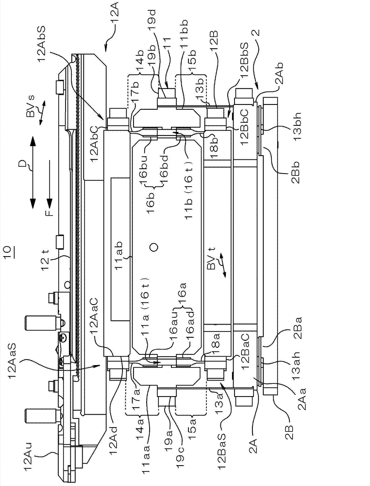
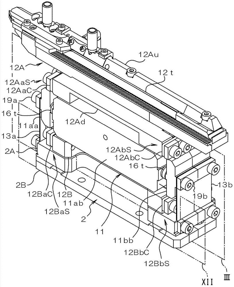
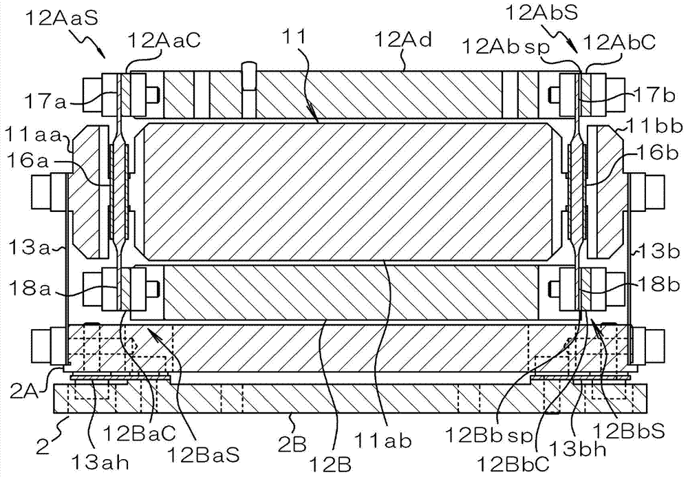
[0095] Next, an embodiment of the vibrating conveying device according to the present invention will be described in detail with reference to the drawings. First, refer to Figure 1 to Figure 5 The overall structure of the first embodiment will be described.
[0096] figure 1 It is a right side view showing the overall structure of the first embodiment, figure 2 is a perspective view showing the overall structure of the first embodiment, image 3 It is a longitudinal sectional view showing other device structures than the conveying block of the first embodiment, Figure 4 It is a front view (a) and a rear view (b) showing the overall structure of the first embodiment, Figure 5 It is a top view which shows the structure of another apparatus other than the conveyance block of 1st Embodiment.
[0097] The vibration conveying device 10 of the present embodiment includes a reference mass body 11 , an upper mass body 12A disposed above the reference mass body 11 , and a lower...
no. 2 approach
[0153] Figure 8 (a) is a sectional view showing the piezoelectric actuators 16a, 16b, the upper connection portions 12AaS, 12AbS, and the lower connection portions 12BaS, 12BbS of the first embodiment, Figure 8 (b) is a sectional view showing piezoelectric actuators 16a", 16b", upper connection parts 12AaS", 12AbS", and lower connection parts 12BaS", 12BbS" of the second embodiment.
[0154] In the second embodiment, as in the first embodiment, the elastic substrates 16s" of the piezoelectric drivers 16a", 16b" are also configured so that the piezoelectric body 16p is formed (the above-mentioned upper piezoelectric drive parts 16au, 16bu and the lower piezoelectric driving parts 16ad, 16bd) are thicker, and the upper parts constituting the upper amplifying springs 17a", 17b" and the lower parts constituting the lower amplifying springs 18a", 18b". Thickness is small.
[0155] However, in this second embodiment, the upper side amplifying spring 17a", The difference from th...
no. 3 approach
[0178] Figure 10 It is a side view showing the schematic structure of the vibratory conveying apparatus concerning 3rd Embodiment of this invention. In the vibrating conveying device 20 of the third embodiment, with respect to the conveying direction F, the anti-vibration springs 13a, 13b before and after the conveying direction D are respectively arranged in the corresponding piezoelectric driving bodies 16a, 16b before and after the conveying direction D. The front is different from the above-mentioned embodiments, but the other structures are the same as the above-mentioned embodiments.
[0179] More specifically, the installation positions of the anti-vibration springs 13a, 13b on the reference mass body 11 are respectively located in the transport direction D, and the corresponding piezoelectric driving bodies 16a, 16b are installed on the reference mass body 11 before and after the transport direction D. In addition, each anti-vibration spring 13a, 13b extends substant...
PUM
 Abstract
Description
Claims
Application Information
 - R&D Engineer
- R&D Manager
- IP Professional
- Industry Leading Data Capabilities
- Powerful AI technology
- Patent DNA Extraction
Browse by: Latest US Patents, China's latest patents, Technical Efficacy Thesaurus, Application Domain, Technology Topic, Popular Technical Reports.
© 2024 PatSnap. All rights reserved.Legal|Privacy policy|Modern Slavery Act Transparency Statement|Sitemap|About US| Contact US: help@patsnap.com