
Power Amplifier Output Power Control Circuit

A power amplifier and output power technology, which is applied in the direction of control/regulation systems, instruments, and electrical variable adjustment, can solve the problems of inaccurate power control, power amplifier power variation, and high design cost.

Active Publication Date: 2017-05-24
LANSUS TECH INC
View PDF5 Cites 0 Cited by
  • Summary
  • Abstract
  • Description
  • Claims
  • Application Information

AI Technical Summary

Problems solved by technology

[0004] Among the above three methods, the third method requires an additional power coupler design, and the design cost is relatively high; the common defect of the first and second methods is that the load mismatch of the power amplifier causes power changes, which are not affected by power control feedback The impact of the ring, resulting in inaccurate power control

Method used


Image

  • Power Amplifier Output Power Control Circuit
  • Power Amplifier Output Power Control Circuit
  • Power Amplifier Output Power Control Circuit

Examples


Embodiment Construction

[0031] In order to make the technical problems, technical solutions and beneficial effects to be solved by the present invention clearer, the present invention will be further described in detail below in conjunction with the accompanying drawings and embodiments. It should be understood that the specific embodiments described here are only used to explain the present invention, not to limit the present invention.

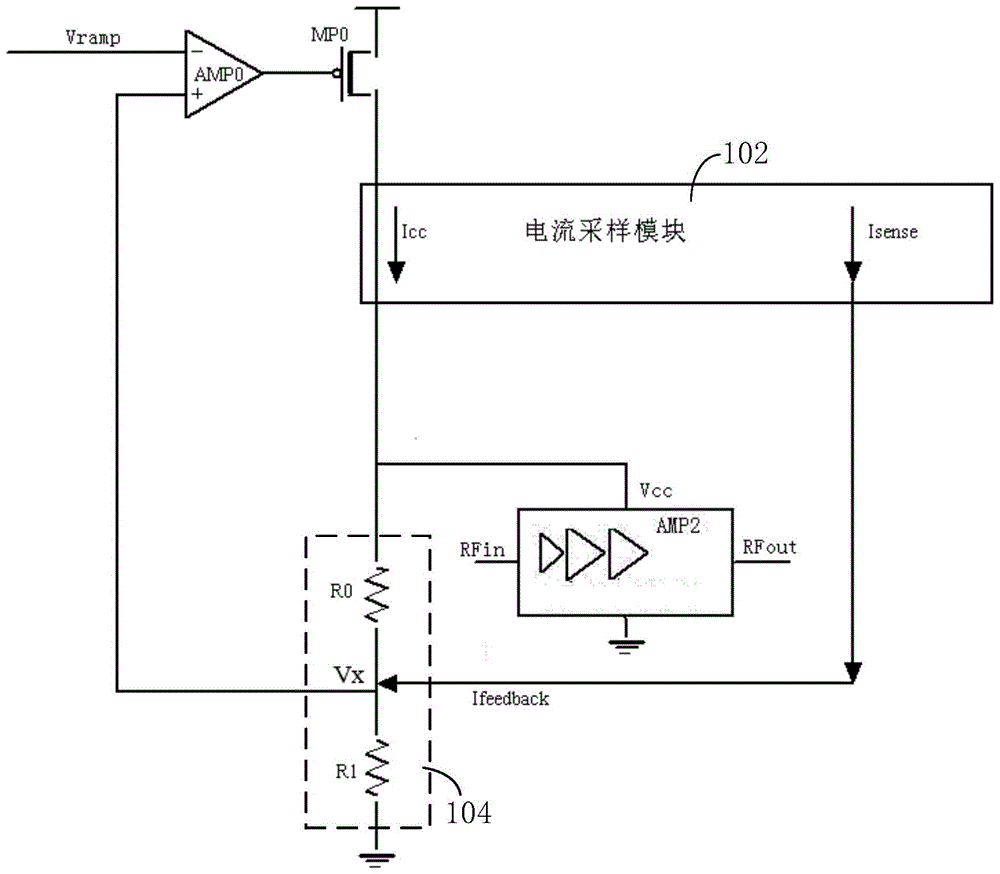
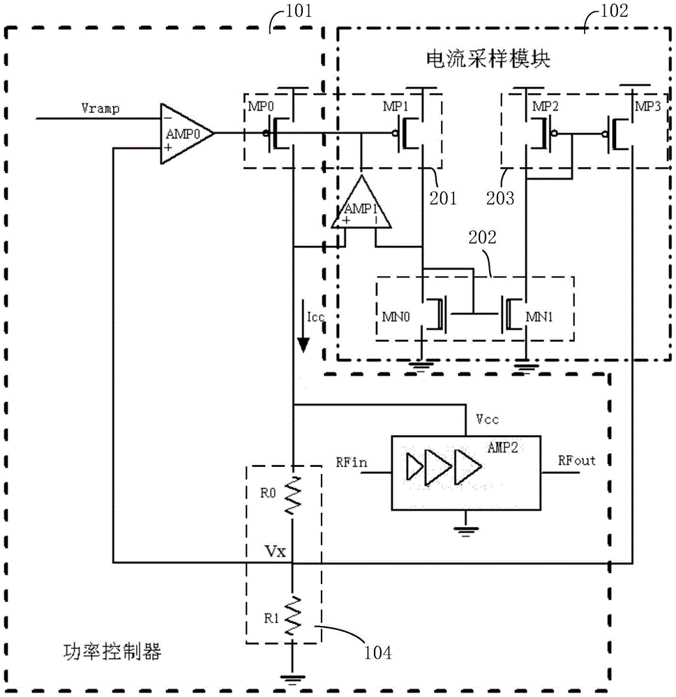
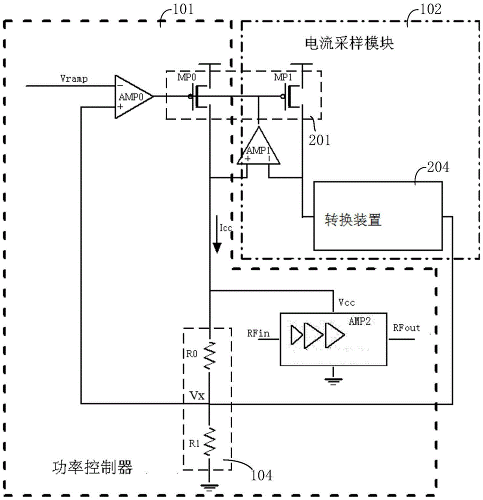
[0032] combine Figures 1 to 4 , the power amplifier output power control circuit includes a first operational amplifier AMP0 , a first PMOS transistor MP0 , a power amplifier AMP2 , a current sampling module 102 and a voltage divider network 104 . Among them, refer to image 3 and 4 , the first operational amplifier AMP0, the first PMOS tube MP0 and the power amplifier AMP2 form a power controller 101, the power amplifier AMP2 is a radio frequency power amplifier, and the power controller 101 controls the voltage of the power supply terminal of the power amplifi...


PUM


Abstract

An output power control circuit of a power amplifier connected to the power amplifier comprises a first operational amplifier (AMP0), a first PMOS transistor, and a current sampling module (102). A negative input end of the first operational amplifier (AMP0) receives a power control signal. A gate of the first PMOS transistor is connected to an output end of the first operational amplifier (AMP0), a source is connected to an external power supply, and a drain is grounded by means of a first voltage offloading network (104). A power supply end of the power amplifier is connected to the drain of the first PMOS transistor, an input end accesses a signal to be amplified and an output end amplifies a signal. The current sampling module (102) samples a current of the first PMOS transistor to form a sampled current, and provides a negative feedback signal to a positive input end of the first operational amplifier (AMP0) according to the sampled current, so that a total power of the power amplifier is unchanged. The technical solutions can maintain a total power of a power amplifier unchanged, so that a correspondence between a load impedance change and an output power is weakened and power control is more accurate.

Description

technical field [0001] The invention belongs to the field of power amplifiers, in particular to a power amplifier output power control circuit. Background technique [0002] In the design of power amplifiers, especially in the design of saturated power amplifiers, it is necessary to control the output power of the power amplifier. In the application environment with different communication strengths, it is required that the power amplifier can output different output powers. [0003] At present, there are three conventional power control methods: First, limit the power supply voltage of the amplifier. The output of the power controller is used as the power supply voltage of the amplifier, and the output of the power controller is controlled by the Ramp signal (ramp signal), so that the power supply voltage of the amplifier changes with the Ramp signal, thereby realizing output power control. Second, the current detection feedback type. By detecting the operating current of...

Claims


Application Information

Patent Timeline
Patent Type & Authority Patents(China)
IPC IPC(8): G05F1/66
CPCG05F1/575
Inventor 赵骞张黎阳龙华程珍娟唐东杰
Owner LANSUS TECH INC
Learn More