
Telescopic outrigger device for tunnel bridge erecting machine

A bridge erecting machine, telescopic technology, applied in the field of telescopic outrigger devices for tunnel bridge erecting machines, can solve the problems of outriggers and main girders, heavy construction workload, long construction period, etc., to achieve fast operation, The effect of convenient operation and simple structure

Active Publication Date: 2016-05-25
CHINA RAILWAY ENG MASCH RES & DESIGN INST CO LTD
View PDF8 Cites 0 Cited by
  • Summary
  • Abstract
  • Description
  • Claims
  • Application Information

AI Technical Summary

Problems solved by technology

[0003] Therefore, the connection method between the outrigger and the main girder in the existing tunnel bridge erecting machine cannot meet the zero distance, negative distance at the tunnel entrance and the erection of the beam in the tunnel, and the construction workload of each tunnel is large and the construction period is long , the construction cost is high, and there are still great safety hazards

Method used


Image

  • Telescopic outrigger device for tunnel bridge erecting machine
  • Telescopic outrigger device for tunnel bridge erecting machine
  • Telescopic outrigger device for tunnel bridge erecting machine

Examples


Embodiment Construction

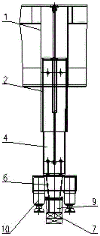
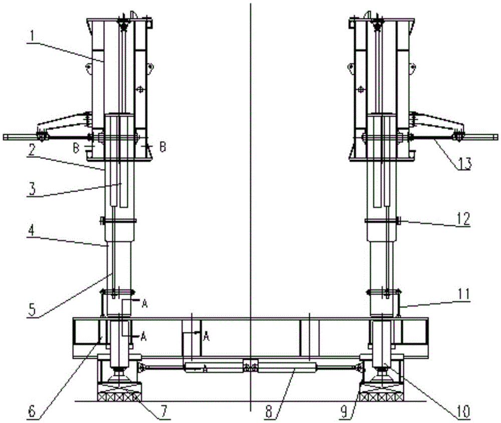
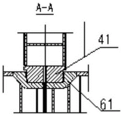
[0027] see Figure 1 to Figure 6 , shows the telescopic outrigger device for the tunnel bridge erecting machine of the present invention.

[0028] The telescopic outrigger device for the tunnel bridge erecting machine includes two sets of primary telescopic structures, two sets of secondary telescopic structures and lower cross-links 6 .

[0029] Each of the first-level telescopic structures is respectively arranged under the main beam outer column 1 of the bridge erecting machine, each of the second-level telescopic structures is arranged under the first-level telescopic structure, and the lower cross-link 6 is arranged between two sets of second-level telescopic structures. below.

[0030] Wherein, the first-level telescopic structure includes a first-level telescopic column 2 and a first-level telescopic oil cylinder 3, and the first-level telescopic column 2 is a hollow casing, the upper end of which can be inserted into the hollow groove of the outer column 1 of the main...


PUM


Abstract

A telescopic landing leg device for tunnel bridge construction machine comprises two sets of first-level telescopic structures, two sets of second-level telescopic structures and lower lateral combination. Each first-level telescopic structure is arranged below a girder outside column of the bridge construction machine, each second-level telescopic structure is arranged below the corresponding first-level telescopic structure, and the lower lateral combination is arranged below the two sets of second-level telescopic structures. Each first-level telescopic structure comprises a first-level telescopic column and a first-level telescopic oil cylinder. An automatic bolt device comprises a connecting beam, a bolt oil cylinder and a first pin shaft, wherein one end of the connecting beam is welded and fixed to the girder outside column, the other end of the connecting beam fixes the oil cylinder body of the bolt oil cylinder, and the tail end of the telescopic rod is connected with the first pin shaft through a hinge pin. Therefore, in the specific using process, the disassembly problem and the standing position problem after landing legs are disassembled do not need to be considered, the telescopic landing leg device has the advantages of being rapid in control, stable in operation, and the working efficiency and the comprehensive utilization rate of the bridge construction machine are improved greatly.

Description

technical field [0001] The invention relates to the technical field of tunnel bridging machines, in particular to a telescopic outrigger device for tunnel bridging machines. Background technique [0002] With the continuous deepening of railway construction, there are a large number of bridge-tunnel connection problems, especially in mountainous areas. At the same time, the tunnel may span the karst cave section, and box girders need to be erected in the tunnel. The tunnel bridge erecting machine is a large-scale universal bridge erection machine that came into being in response to this phenomenon. Usually, the middle leg of the bridge erecting machine is in order to meet the passage of the box girder on the one hand, and on the other hand to meet the support requirements of the hanging beam and the beam drop operation. The middle leg is a C-shaped structure, because the C-shaped structure has to bear additional bending moments , so the C-shaped outrigger is relatively larg...

Claims


Application Information

Patent Timeline
Patent Type & Authority Patents(China)
IPC IPC(8): E01D21/00E01D21/06
CPCE01D21/00
Inventor 刘俊生张智莹周发扬吴春慧孟凡田徐超李玮陈国瑞
Owner CHINA RAILWAY ENG MASCH RES & DESIGN INST CO LTD
Learn More