
Dynamic sealing device

A technology of dynamic sealing and sealing cavity, which is applied in the direction of engine sealing, engine components, mechanical equipment, etc. It can solve the problem of difficulty in ensuring relative position, axial displacement, radial displacement caused by the concentricity of the axis and the end surface of the first equipment. Problems such as angular displacement caused by jumping can be eliminated to achieve the effect of improving dynamic sealing performance

Active Publication Date: 2015-06-17
大连杜尔环保科技有限公司
View PDF8 Cites 0 Cited by
  • Summary
  • Abstract
  • Description
  • Claims
  • Application Information

AI Technical Summary

Problems solved by technology

This type of equipment generally requires high temperature heating, and the thermal expansion factor of the equipment may cause the axial displacement of two relatively moving parts due to thermal expansion, the radial displacement caused by the concentricity of the axis, and the angular displacement caused by the beating of the end face of the first equipment. Displacement so that it is difficult to ensure that the relative position of two parts in relative motion remains constant
Obviously, the static sealing mechanism commonly used in the industry cannot meet the demand. In view of this, it is very necessary to provide a dynamic sealing device to solve the existing problems

Method used


Image

  • Dynamic sealing device
  • Dynamic sealing device

Examples


Embodiment Construction

[0023] In order to make the technical means, creative features, goals and effects achieved by the present invention easy to understand, the present invention will be further described below in conjunction with specific embodiments.

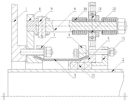
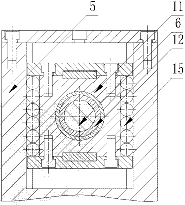
[0024] in, figure 1 is a sectional structure diagram of the dynamic sealing device, figure 2 It is a partial cross-sectional view of the bearing seat in the dynamic sealing device, in figure 1 In the shown structure, the figure only illustrates the structure in which the dynamic sealing device is arranged at one end of the equipment to be sealed.

[0025] The dynamic sealing device seals the medium flow path between the relatively moving first device 1 and the second device 2 . The first device is defined as a dynamic device, and the second device is defined as a static device. The above definition will be further described below.

[0026] The moving equipment rotates at a preset speed along the axis of the static equipment. In order to realiz...


PUM


Abstract

The invention discloses a dynamic sealing device which is used for achieving sealing between relatively moving equipment. The dynamic sealing device comprises a flexible sealing pipe, a first connecting part, a second connecting part and a compensating arm, wherein the first connecting part and the second connecting part are arranged at the two ends of the flexible sealing pipe respectively, and the compensating arm is connected between the first connecting part and the second connecting part. The first connecting part is fixed to the first equipment, the second equipment is inserted into the flexible sealing pipe inwards from the second connecting part, and the compensating arm allows the first equipment and the second equipment to conduct relative displacement in the axial direction, the radial direction and the angle direction of the first equipment and the second equipment. The dynamic sealing device used for achieving sealing between the two sets of relatively moving equipment comprises the flexible sealing pipe which can be bent to deform, the first connecting part arranged at one end of the flexible sealing pipe and the second connecting part arranged at the other end of the flexible sealing pipe; because the first connecting part and the second connecting part can perform relative deviation in the axial direction, the radial direction and the angle direction, relative deviation, in the axial direction, the radial direction and the angle direction, of the two sets of relatively moving equipment can be effectively compensated for, and the dynamic sealing performance of the dynamic sealing device can be improved.

Description

technical field [0001] The invention relates to a mechanical sealing device, in particular to a dynamic sealing device used for sealing between two relative moving devices. Background technique [0002] In many manufacturing industries, sealing performance, as an extremely important characteristic, directly determines the quality of equipment technology. As we all know, the seals of the more common mechanical equipment are usually static seals, which are used to ensure the tightness between two relatively static parts, and the static seal technology has been relatively mature. [0003] At present, for many equipment that needs to move in the production process, it is often necessary to ensure the sealing between two relatively moving parts in the equipment. This type of equipment generally requires high temperature heating, and the thermal expansion factor of the equipment may cause the axial displacement of two relatively moving parts due to thermal expansion, the radial d...

Claims


Application Information

Patent Timeline
IPC IPC(8): F16J15/16
CPCF16J15/184F16J15/52
Inventor 杨宝仁
Owner 大连杜尔环保科技有限公司
Learn More