
Coulomb damper

A damper and damping technology, which is applied in the field of damping shock absorbers, can solve problems such as changes in elastic characteristics and damping characteristics, difficult damping, and large damping fluctuations, so as to avoid differences in elastic characteristics, reduce axial dimensions, eliminate The effect of damping fluctuations

Active Publication Date: 2015-06-17
江苏欣捷诺环境工程技术有限公司
View PDF5 Cites 3 Cited by
  • Summary
  • Abstract
  • Description
  • Claims
  • Application Information

AI Technical Summary

Problems solved by technology

[0003] 1) The damper is composed of two sets of damping pairs and two compression springs, with a large structural size;
[0004] 2) The pre-tightening force of the compression spring cannot be easily adjusted on demand;
[0005] 3) Due to the inevitable differences in the elastic properties of the two compression springs arranged up and down respectively, during the reciprocating movement with the overall structure, the damping produced by the two springs alternately being compressed and released is difficult to be consistent (commonly known as large damping fluctuations) ;
[0006] 4) In the case of axial vibration, there is a risk of rigid short circuit caused by mechanism locking due to excessive compression of the compression spring, which makes the damping force exceed the threshold, and is not suitable for use in strong vibration environments
[0007] 5) When there is an inclined angle between the axial direction of the shock absorber and the vibration direction, the elastic characteristics and damping characteristics of the shock absorber will change with the change of the angle, resulting in unstable vibration system parameters

Method used


Image

  • Coulomb damper
  • Coulomb damper
  • Coulomb damper

Examples


Embodiment 1

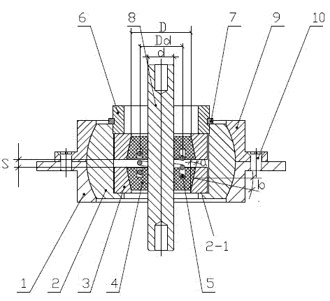
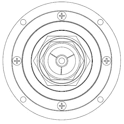
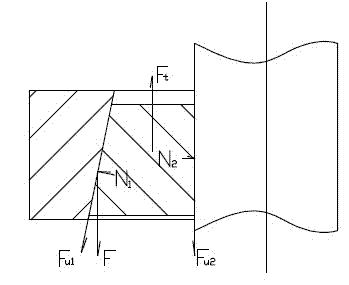
[0025] Coulomb damper of the present embodiment such as figure 1 As shown, it includes a shell seat in which a pair of truncated cone mounting seats 3 are installed. The shell seat consists of an upper shell 9 and a lower shell 1 with an internal spherical concave, and a ball seat 2 that forms a spherical hinge structure with the upper and lower shells. Composition, the mating ends of the upper shell 9 and the lower shell 1 radially outwardly extend out of the flange respectively, and are fixedly connected by screws 10 . The center of the ball seat 2 has an inner hole for installing the truncated cone mounting seat, one end of the inner hole has an axial limit shoulder 2-1, and the other end has an adjusting thread. The two cone mounts 3 are loaded into the inner hole of the ball seat 2 at the opposite position of the large ends of the taper holes, and there is an adjustment interval S between them. The bottom surface of the lower cone mount is positioned at the limit stop sho...


PUM


Abstract

The invention relates to a coulomb damper, belonging to the technical field of damping vibration absorbers. The coulomb damper comprises a housing seat, wherein a pair of frustum mounting seats is mounted in the housing seat; damping pairs are mounted in tapered holes of the frustum mounting seats; center shafts penetrate through the centers of the damping pairs; the two frustum mounting seats are mounted in an inner hole of the housing seat with the large ends of the tapered holes opposite to each other; an adjustment interval is reserved in the inner hole; damping pressure springs are mounted between the two pairs of damping pairs; the housing seat consists of an upper housing, a lower housing and a ball seat; the upper housing and the lower housing are provided with inner ball concaves; a spherical hinge structure is formed by the upper housing, the lower housing and the ball seat; and a ball seat center penetrable hole is provided with adjustment threads for mounting the frusta mounting seats. The coulomb damper completely eliminates damping waves and has ideal following character; the phenomenon of dead lock is avoided; and the axial size of the coulomb damper is significantly reduced; the structure is very compact; and the operation is very convenient.

Description

technical field [0001] The invention relates to a damper, in particular to a Coulomb damper, and belongs to the technical field of damping and shock absorbers. Background technique [0002] The damper is a key component of the vibration damping device, because damping plays a pivotal role in the vibration damping system. Coulomb damping is a type of damping with high stability and good consistency. The vibration isolator disclosed in the "Composite Damping Vibration Isolator" with the application number ZL85 1 03709 Chinese Patent has applied the Coulomb damping structure, although according to the introduction It can "make the vibration isolation system properly damped in the harsh vibration and shock environment, provide good isolation effects in the directions of the three coordinate axes, and effectively limit the resonance amplitude", but with the development of technology and the reduction of With the improvement of vibration and vibration isolation requirements, the ...

Claims


Application Information

Patent Timeline
Patent Type & Authority Applications(China)
IPC IPC(8): F16F7/00
CPCF16F7/104
Inventor 吕哲陈昱辰
Owner 江苏欣捷诺环境工程技术有限公司
Learn More