
A dynamic detection device and implementation method for shape and position parameters of elevator guide rails

A technology for elevator guide rails and dynamic detection, applied in the direction of measuring devices, electrical devices, optical devices, etc., can solve problems such as poor stability and large data errors, and meet the requirements of detection accuracy, clear circuit connection relationship, and mechanical structure simple effect

Active Publication Date: 2017-06-27
FUJIAN SPECIAL EQUIP TESTING RES INST
View PDF5 Cites 0 Cited by
  • Summary
  • Abstract
  • Description
  • Claims
  • Application Information

AI Technical Summary

Problems solved by technology

[0002] At present, none of the elevator guide rail verticality testing instruments used at home and abroad adopts the corresponding mechanical fixing mechanism, and its data receiving devices are all implemented manually, so the stability is poor, and the measured data error is large; It is stipulated that the verticality embedded detection system of the elevator guide rail needs to measure the change of the small displacement, that is, at least within the range of 0.1mm, so the sensitivity of the selected detector must be high. In order to achieve the above-mentioned detection accuracy and mechanical structure fixing requirements, it is the research of the present invention Object

Method used


Image

  • A dynamic detection device and implementation method for shape and position parameters of elevator guide rails
  • A dynamic detection device and implementation method for shape and position parameters of elevator guide rails
  • A dynamic detection device and implementation method for shape and position parameters of elevator guide rails

Examples


Embodiment Construction

[0021] In order to make the above-mentioned features and advantages of the present invention more comprehensible, the following specific embodiments are described in detail with reference to the accompanying drawings.

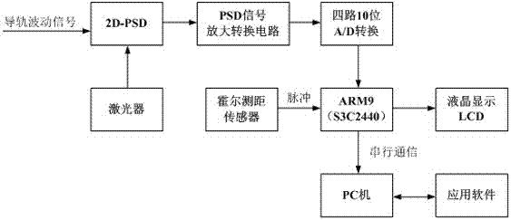
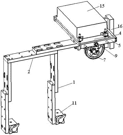
[0022] refer to Figure 1 to Figure 4 , the present invention relates to a dynamic detection device for shape and position parameters of an elevator guide rail, comprising a detector and a mechanical fixing bracket for installing the detector on the elevator guide rail, the hardware of the detector includes a laser, a two-dimensional position sensitive device (2D -PSD), PSD signal amplification conversion circuit, A / D conversion module, Hall ranging sensor, ARM9 chip, liquid crystal display LCD and PC, the laser is connected to the PSD signal amplification conversion circuit through a two-dimensional position sensitive device, Described PSD signal amplifying conversion circuit is connected with ARM9 chip circuit through A / D conversion module, and described ARM9...


PUM


Abstract

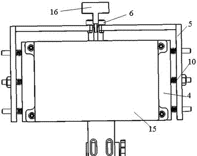
The invention discloses a dynamic detection device for shape and position parameters of an elevator guide rail, which includes a detector and a mechanical fixing bracket for installing the detector on the elevator guide rail. The hardware of the detector includes a laser, a two-dimensional position sensitive device, a PSD Signal amplification conversion circuit, A / D conversion module, Hall distance measuring sensor, ARM9 chip, liquid crystal display LCD and PC; the mechanical fixing bracket includes an adjustable longitudinal support arm connected to the upper beam of the car, and the The upper end of the adjustable longitudinal support arm is connected with an adjustable horizontal support arm, and the adjustable horizontal support arm is connected with a guide rail tester chassis for installing a tester through a fixed slide rail and a sliding shoe on the side of the guide rail, and the guide rail tester chassis A U-shaped guide rail detector chassis clamping arm is connected to the outer periphery of the guide rail detector chassis, and the front side of the guide rail detector chassis clamping arm is provided with two guide rail side clamping rollers that are respectively located on the two sides of the elevator guide rail. The invention has simple, firm and reliable mechanical structure, clear and simple circuit connection relationship of the detector, and can effectively meet the requirement of detection accuracy.

Description

technical field [0001] The invention relates to a dynamic detection device for shape and position parameters of an elevator guide rail and a realization method, and belongs to the technical field of inspection and detection of special equipment. Background technique [0002] At present, none of the elevator guide rail verticality testing instruments used at home and abroad adopts the corresponding mechanical fixing mechanism, and its data receiving devices are all implemented manually, so the stability is poor, and the measured data error is large; It is stipulated that the verticality embedded detection system of the elevator guide rail needs to measure the change of the small displacement, that is, at least within the range of 0.1mm, so the sensitivity of the selected detector must be high. In order to achieve the above-mentioned detection accuracy and mechanical structure fixing requirements, it is the research of the present invention Object. Contents of the invention ...

Claims


Application Information

Patent Timeline
Patent Type & Authority Patents(China)
IPC IPC(8): G01B11/00G01B11/26G01B7/02
Inventor 郑祥盘刘季能曹晨洁李晓宁孙彦锋黄文翰吴城汀
Owner FUJIAN SPECIAL EQUIP TESTING RES INST
Learn More