
Chain and chain guide plate

A chain and plate technology, applied in the direction of belts/chains/gears, chain elements, transmission chains, etc., can solve problems such as noise, and achieve the effects of avoiding the increase in the number of blocks, suppressing noise, and improving contact balance

Active Publication Date: 2015-06-03
TSUBAKIMOTO CHAIN CO
View PDF4 Cites 3 Cited by
  • Summary
  • Abstract
  • Description
  • Claims
  • Application Information

AI Technical Summary

Problems solved by technology

[0007] However, when using the inner guide G to guide the chain 500, there are other problems in the existing chain 500 as follows, such as Figure 11 As shown, since there is a gap D formed between the guide sliding contact portions 524 of each guide plate 520, the plurality of guide sliding contact portions 524 intermittently collide with the guide block surface G1 of the inner guide G when the chain moves, noise due to the intermittent collision

Method used


Image

  • Chain and chain guide plate
  • Chain and chain guide plate
  • Chain and chain guide plate

Examples


Embodiment

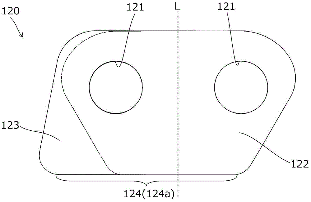
[0031] Below, according to Figure 1~4 The chain 100 which concerns on 1st Embodiment of this invention is demonstrated.

[0032] The chain 100 of the first embodiment is configured as a timing chain installed in a timing system for an automobile engine, as figure 2 As shown, the chain moves on a predetermined track in a state where it is wound on a plurality of sprockets (not shown) and the inner guide G having a flat guide block surface G1 guides the curved inner peripheral side of the chain. . The inner guide G is configured as a fixed guide fixed to a peripheral portion such as an engine block or as a swing guide that is pressed toward the chain 100 side by a tensioner swingably attached to the peripheral portion.

[0033] Such as figure 1 As shown in the chain 100 , a plurality of first plate arrays 110 and a plurality of second plate arrays 140 are alternately arranged and flexibly connected in the chain length direction by half a pitch.

[0034] Such as figure 1...


PUM


Abstract

The invention provides a chain and a chain guide plate that suppress occurrence of noise during chain traveling while attaining a reduction in costs and also attaining space saving. A chain includes first plate rows and second late rows. Each of the first plate rows includes a guide plate including a guide slide contact section for coming into slide contact with an inner side guide. The guide slide contact section extends in a chain longitudinal direction to be asymmetrical relative to an imaginary center line. During guiding by the inner side guide, lines drawn by the guide slide contact sections of a plurality of the guide plates are continuous in the chain longitudinal direction.

Description

technical field [0001] The present invention relates to a first plate row and a second plate row including a plurality of flat plates arranged side by side in the chain width direction, which are alternately arranged with half a pitch in the chain length direction, thereby being bendably connected. A chain and a chain guide plate used for the chain. Background technique [0002] In the past, such as Figure 10 As shown, the following chain 500 is known (for example, refer to Patent Document 1), in which the first flat row 510 and the second flat row 540 are alternately arranged with a half-pitch in the chain length direction, and the connecting pin 560 is used to bend the chain. In connection, the first plate row 510 includes a plurality of plates 520 and 530 arranged in parallel in the chain width direction, and the second plate row 540 includes a plurality of plates 550 arranged in parallel in the chain width direction. [0003] Here, various methods are known as a method...

Claims


Application Information

Patent Timeline
Patent Type & Authority Applications(China)
IPC IPC(8): F16G13/00F16G15/00
CPCF16G13/07F16G15/00F16G13/04F16G13/08F16G13/06F16H7/18F16G13/02F16H7/06
Inventor 石田裕树菅沢重信
Owner TSUBAKIMOTO CHAIN CO
Learn More