Rapid blade installation structure

A technology for installing structure and fan blades, which is applied in the field of ceiling fans, can solve the problems of troublesome fixing of fan blades and blade forks, inconvenient disassembly, and low efficiency, and achieve the effect of firm, safe and reliable structure, easy disassembly and adjustment, and simple and fast assembly

Inactive Publication Date: 2015-06-03
ZHONGSHAN WEIHE ELECTRICAL APPLIANCES
View PDF0 Cites 0 Cited by
  • Summary
  • Abstract
  • Description
  • Claims
  • Application Information

AI Technical Summary

Problems solved by technology

The fan blade of the ceiling fan is driven by the motor to make the surrounding air flow to generate wind. In the current common structure on the market, the rotating part of the motor is provided with a leaf fork, and the fan blade is installed on the leaf fork through a screw locking structure, so as to Realize the transmission connection with the motor. However, the disadvantage of this type of structure is that the fixing of the fan blade and the leaf fork is more troublesome, requires tools, and the efficiency is not high. At the same time, it is not easy to disassemble after fixing, which is inconvenient to use. However, if snap-fit ​​or other fast-installation structures are used, the safety and reliability of the fan blades that rotate at different speeds during use cannot be well guaranteed. It can be seen that there is a need for further improvement.

Method used


Image

  • Rapid blade installation structure
  • Rapid blade installation structure
  • Rapid blade installation structure

Examples


Embodiment Construction

[0013] In order to make the object, technical solution and advantages of the present invention clearer, the present invention will be further described in detail below in conjunction with the accompanying drawings and embodiments. It should be understood that the specific embodiments described here are only used to explain the present invention, not to limit the present invention.

[0014] The specific realization of the present invention is described in detail below in conjunction with specific embodiment:

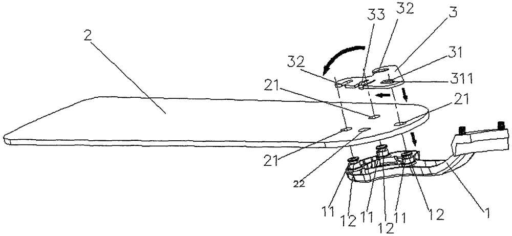
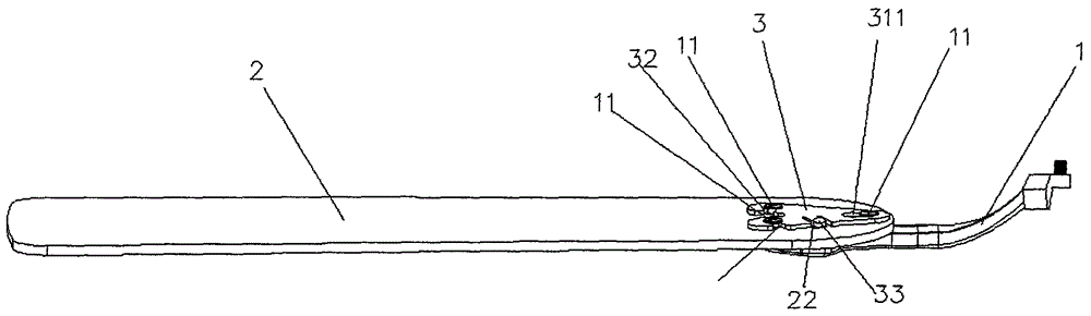
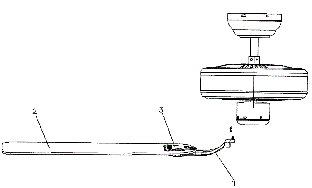
[0015] refer to figure 1 As shown, a fan blade quick installation structure provided by the present invention includes a leaf fork 1, a fan blade 2 and a clamping plate 3, wherein at least three raised positioning card platforms 11 are provided on one side of the leaf fork 1, The fan blade 2 is provided with at least three through holes 21 corresponding to the positioning card table 11, and a ring groove 12 is provided at the head of the positioning card table 11; the ca...


PUM


Abstract

The invention discloses a rapid blade installation structure. The rapid blade installation structure comprises a blade fork, a blade and a clamping plate; one side of the blade fork is provided with at least three protruding positioning clamping platforms; at least three through holes which are corresponding to the positioning clamping platforms are correspondingly arranged on the blade; the heads of the positioning clamping platforms are provided with a surrounding annular grooves; the clamping plate is provided with clamping holes and a plurality of lateral clamping openings; the number of the clamping holes is identical to that of the positioning clamping platforms; heads of the positioning clamping platforms respectively penetrate and extend out of the corresponding through holes; the clamping plate and one annular groove of one positioning clamping platform are clamped through the clamping hole; the lateral clamping openings are clamped into the annular grooves of the other positioning clamping platforms from the lateral side in a rotary mode. According to the rapid blade installation structure, the blade and the blade fork are fixed through the clamping plate by locking after being clamped, the assembling is simple and rapid, real-time detachment and adjustment is convenient, the structure is firm, safe and reliable, a mode of auxiliary positioning through a positioning protruding point is adopted, the safety is further reinforced, and the rapid blade installation structure is particularly suitable for rotary blades.

Description

technical field [0001] The invention relates to a ceiling fan, in particular to a fast installation structure for fan blades of the ceiling fan. Background technique [0002] The ceiling fan can be hung on the ceiling to supply air to the indoor environment. It is a product with good heat dissipation function, energy saving and power saving, and decorative effect, and is very popular in the market. The fan blade of the ceiling fan is driven by the motor to make the surrounding air flow to generate wind. In the current common structure on the market, the rotating part of the motor is provided with a leaf fork, and the fan blade is installed on the leaf fork through a screw locking structure, so as to Realize the transmission connection with the motor. However, the disadvantage of this type of structure is that the fixing of the fan blade and the leaf fork is more troublesome, requires tools, and the efficiency is not high. At the same time, it is not easy to disassemble after...

Claims


Application Information

Patent Timeline
Patent Type & Authority Applications(China)
IPC IPC(8): F04D29/34
CPCF04D29/36
Inventor 黄渊
Owner ZHONGSHAN WEIHE ELECTRICAL APPLIANCES
Why Eureka
Try Eureka