engine controller

A technology for engine controllers and actuators, which is applied in the direction of engine control, engine components, combustion engines, etc., and can solve problems such as cost concentration, unexpected shutdown of internal combustion engines, and failure of magnetic actuators

Inactive Publication Date: 2020-03-06
MAN ENERGY SOLUTIONS SA
View PDF11 Cites 0 Cited by
  • Summary
  • Abstract
  • Description
  • Claims
  • Application Information

AI Technical Summary

Problems solved by technology

However, this is only possible if maintenance work is to be carried out on the internal combustion engine anyway
There is therefore the risk that the magnetic actuator fails during operation outside regular maintenance intervals of the internal combustion engine and thus leads to an undesired shutdown of the internal combustion engine and thus to its cost-intensive downtime.

Method used


Image

  • engine controller

Examples


Embodiment Construction

[0032] The invention relates to an engine controller for an internal combustion engine, especially a four-stroke internal combustion engine operating at a medium speed (which uses diesel or heavy oil or gas as fuel).

[0033] Such an internal combustion engine is preferably a marine engine.

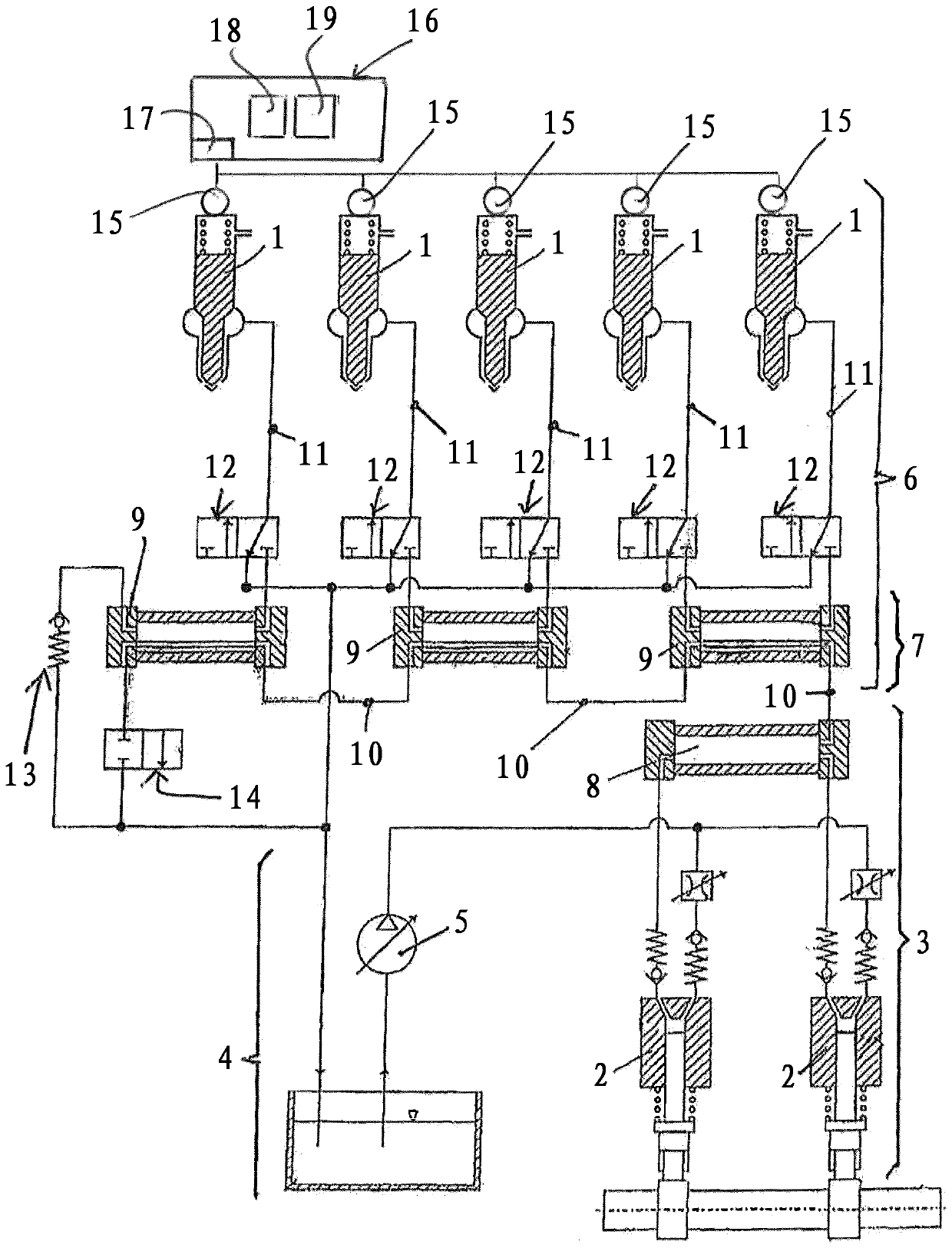
[0034] Such an internal combustion engine typically has a common rail fuel supply device, and its basic structure is familiar to the professionals mentioned here and has been referred to figure 1 To illustrate. Such a fuel supply device has a magnetic actuator 15 which can be controlled by an engine controller 16. in figure 1 , Such a magnetic actuator 15 is shown in the area of ​​the ejector 1.

[0035] In the meaning of the present invention, it is proposed that the engine controller 16 includes a device to automatically determine the value of at least one magnetic characteristic parameter of the magnetic actuator 15 built in the fuel supply device when the internal combustion engine is sto...


PUM


Abstract

The invention relates to an engine controller, an engine controller (16) for an internal combustion engine, in particular an internal combustion engine operated on diesel or heavy oil or on gas, wherein the internal combustion engine has a fuel supply with a magnetic actuator, in particular a common rail fuel supply device, wherein the engine controller (16) includes means (17, 18, 19) to automatically determine at least one magnetic The actual value of the characteristic parameter is evaluated in such a way that if the corresponding actual value deviates from the corresponding nominal value by less than a predetermined amount, then the engine controller (16) automatically deduces that the magnetic actuator is working normally, otherwise if the corresponding actual If the value deviates from the corresponding nominal value by more than a predetermined amount, the engine controller (16) automatically infers a malfunctioning magnetic actuator.

Description

Technical field [0001] The invention relates to an engine controller according to the preamble of claim 1. Background technique [0002] figure 1 The basic structure of a common rail fuel supply device known from the prior art of an internal combustion engine is shown. This construction is known from DE 101 57 135 B4. in this way, figure 1 The common rail fuel supply equipment includes at least one injector 1 for each cylinder of the internal combustion engine. Via the injector 1, fuel can be injected into each of the cylinders of the internal combustion engine. In addition, the common rail fuel supply equipment includes a pump device 3 having at least one low-pressure pump 5, at least one high-pressure pump 2 and a high-pressure pump storage 8 in order to deliver fuel from the low-pressure area 4 of the common-rail fuel supply equipment to its high-pressure area 6 , Wherein a pressure storage system 7 permanently under high pressure is provided in the high pressure region 6...

Claims


Application Information

Patent Timeline
Patent Type & Authority Patents(China)
IPC IPC(8): F02D41/22
CPCF02D41/221F02D19/025F02D19/0623F02D19/0657F02D19/0684F02D41/20F02M65/00F02M21/0245F02M21/0254F02D2041/2086F02D41/042F02D41/0027F02M63/0285Y02T10/40Y02T10/30F02D41/22
Inventor L.迈尔C.施罗特H.韦伦克特C.胡赫尔S.克恩D.科瓦列夫F.胡斯利克A.韦伯
Owner MAN ENERGY SOLUTIONS SA
Why Eureka
Try Eureka