
a vibration isolation ditch

A vibration isolation and ditch technology, which is applied in protection devices, buildings, infrastructure engineering, etc., can solve the problems that the vibration isolation ditch cannot bear the load and cannot be installed under the road, and achieve the effect of reducing the transmission of vibration waves

Active Publication Date: 2016-06-08
HUAXIN CONSULTATING CO LTD
View PDF7 Cites 4 Cited by
  • Summary
  • Abstract
  • Description
  • Claims
  • Application Information

AI Technical Summary

Problems solved by technology

[0003] The purpose of the present invention is to solve the problem that the traditional hollow vibration isolation ditch cannot bear load and cannot be installed under the road, and provides a filled vibration isolation ditch that can be installed under the road

Method used


Image

  • a vibration isolation ditch
  • a vibration isolation ditch
  • a vibration isolation ditch

Examples


Embodiment 1

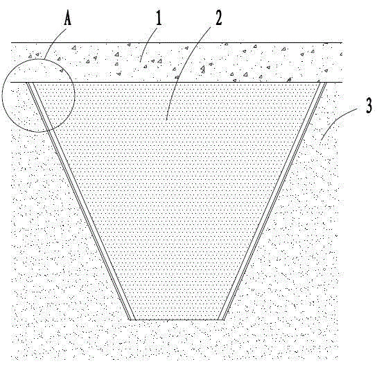
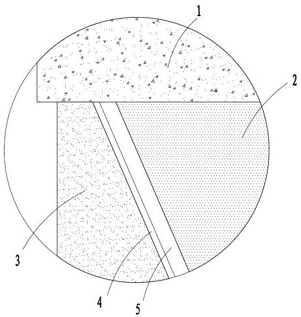
[0024] Embodiment 1: A kind of vibration isolation ditch, such as figure 1 , 2 shown. In this structure, a trapezoidal ditch with a trapezoidal interface is dug in the plain soil layer 3 of the subgrade. The ditch body is wide at the top and narrow at the bottom. The two side walls of the ditch body are successively laid with polystyrene boards 4 with a thickness of 40mm and reinforced concrete boards with a thickness of 100mm from bottom to top. Inside the ditch is a sand and gravel filling layer 2, which is flush with the ditch mouth. Concrete pavement 1 is poured above the ditch body, and the width of the concrete pavement is greater than the width of the ditch body.

Embodiment 2

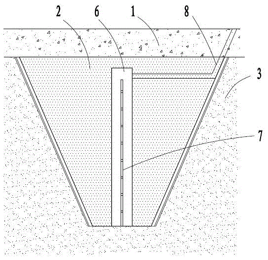
[0025] Embodiment 2: A kind of vibration isolation ditch with vibration isolation water tank, such as image 3 shown. In this structure, a trapezoidal ditch with a trapezoidal interface is dug in the plain soil layer 3 of the subgrade. The ditch body is wide at the top and narrow at the bottom. The two side walls of the ditch body are successively laid with polystyrene boards 4 with a thickness of 40mm and reinforced concrete boards with a thickness of 100mm from bottom to top. Inside the ditch is a sand and gravel filling layer 2, which is flush with the ditch mouth. Concrete pavement 1 is poured above the ditch body, and the width of the concrete pavement is greater than the width of the ditch body.

[0026] A vibration-isolation water tank 6 is buried in the sand-stone filling layer 2. The bottom of the vibration-isolation water tank is arranged on the bottom surface of the ditch body. The top of the vibration-isolation water tank does not exceed the top surface of the sa...

Embodiment 3

[0028] Embodiment 3: A kind of vibration isolation ditch with double clapboard vibration isolation water tank, such as image 3 shown. Two partitions 7 are arranged in parallel in the vibration-isolation water tank 6 of this structure, and the damping holes of the two partitions are mutually misaligned. The rest of the structure of this embodiment is the same as that of Embodiment 2. Utilizing the misalignment of the vibration-damping holes of the two partitions, a complex shearing action is formed at the vibration position of the water body to achieve the effect of rapidly absorbing the vibration energy.


PUM


Abstract

The invention relates to an isolation trench which solves the problem that the traditional internally hollow isolation trench cannot be arranged under roads for the reason that the internally hollow isolation trench cannot bear loads. According to the isolation trench, a trench body with a trapezoidal section wide at top and narrow at bottom is arranged in a roadbed pure soil layer in a digging manner; polystyrene plates and reinforced concrete plates are paved in the skew walls on two sides of the trench body from upper part to lower part in sequence; a gravel filling layer flushing with the trench opening is in the trench body; a concrete road surface is poured above the gravel filling layer which is regarded as a base. The isolation trench disclosed by the invention is filled by gravels, so that the isolation trench has the load bearing capacity, and can be arranged under roads. Meanwhile, a vibration isolation tank is arranged in the gravel filling layer, so that transmitted vibration waves can be effectively adsorbed, and the transmission of the vibration waves on two sides of the isolation trench is further reduced.

Description

technical field [0001] The invention belongs to the technical field of building vibration isolation, and relates to a vibration isolation ditch arranged under a road. Background technique [0002] Vibration isolation ditch is a common engineering method to prevent or change the propagation of peripheral vibration waves to the shielded area, thereby reducing the ground vibration in the shielded area. The principle of vibration isolation trench is based on the reflection and scattering of waves. When a propagating wave encounters the interface between two different elastic media, part of the incident wave is reflected back to the first medium, and the other part of the wave is transmitted to the second medium, which is the phenomenon of reflection and transmission of elastic waves. The vibration isolation groove can also change the frequency distribution of the wave, disperse the energy of the main frequency band of the wave, and help reduce the vibration effect of the vibrat...

Claims


Application Information

Patent Timeline
Patent Type & Authority Patents(China)
IPC IPC(8): E02D31/08
CPCE02D31/08
Inventor 竹影胡征宇姚云龙张珩章昊南
Owner HUAXIN CONSULTATING CO LTD
Learn More