
Vibration control device and method for slings of suspension bridge

A technology for suspension bridges and slings, which is applied in the field of vibration control devices for suspension bridges and slings, which can solve the problems of easy aging, slow attenuation, and poor durability, and achieve convenient installation and maintenance, improve modal damping, and improve vibration order Effect

Active Publication Date: 2015-06-03
中铁桥研科技有限公司 +2
View PDF7 Cites 9 Cited by
  • Summary
  • Abstract
  • Description
  • Claims
  • Application Information

AI Technical Summary

Problems solved by technology

It plays the role of rigid restraint when the double suspension cables vibrate in anti-phase, so that the free vibration length of the suspension cables becomes 1 / n of the original, and the frequency increases to n times of the original, which is beneficial to reduce the wind-induced vibration of the suspension cables. However, since the vibration damping frame does not produce energy dissipation, once the sling vibrates, the vibration will last for a long time and attenuate slowly, resulting in fatigue damage to the cable body, anchor head and vibration damping frame of the sling
[0004] In addition, there are some reports and applications of vibration control by dampers. Among them, the patent No. ZL201420222127.3 is a damping and vibration-reducing frame for slings. When multiple slings move together, the damping and vibration-reducing frame can provide certain Damping, but when the sling moves in the opposite phase mode, this damping shock mount is equivalent to a rigid shock mount and cannot provide damping and vibration reduction
The patent No. ZL201020161536.9 is a large-span suspension bridge suspender cable shock absorber, which uses a shock absorber to control the vibration of the suspension. High damping rubber, prone to aging and poor durability in harsh real bridge environments
Therefore, there is currently no vibration-damping structure that can simultaneously control in-phase vibration and anti-phase vibration

Method used


Image

  • Vibration control device and method for slings of suspension bridge
  • Vibration control device and method for slings of suspension bridge
  • Vibration control device and method for slings of suspension bridge

Examples


Embodiment Construction

[0030] The present invention will be further described in detail below in conjunction with the drawings and embodiments.

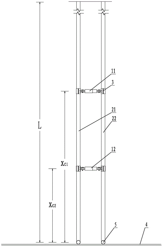
[0031] Such as image 3 with Figure 4 As shown, a vibration control device for a suspension bridge sling is arranged between two slings side by side. The two slings are a first sling 21 and a second sling 22, and one end of each sling is moved through The hinge 5 is fixed to the main beam 4. This control device includes several dampers. The dampers are durable dampers, including oil dampers, high damping rubber dampers, shape memory alloy dampers, magnetorheological dampers, friction dampers, and viscous dampers. Dampers, electromagnetic dampers. The dampers are arranged in sequence along the sling, and both ends of each damper are respectively fixed to a sling by a cable clamp 3. Among them, the masses of the two slings are not equal, and the cable forces of the two slings are not equal. In this embodiment, the number of dampers between the two slings is ...


PUM


Abstract

The invention discloses a vibration control device and a vibration control method for slings of a suspension bridge. The vibration control device is arranged between the two abreast slings; one end of each sling is fixedly arranged on a main beam through a moving hinge; dampers are sequentially arranged along each sling; two ends of each damper are fixed with the corresponding sling through a sling clamp respectively. The vibration control method comprises the following steps: firstly, adjusting the frequency of one of the two abreast slings to achieve that the two slings are different in frequency; secondly, arranging a plurality of dampers between the two slings; finally, optimizing the mounting position of each damper according to the vibration mode control requirements of the slings. According to the device and the method, in-phase vibration generated by the double abreast slings is eliminated, and inverse phase vibration is restrained.

Description

Technical field [0001] The invention relates to the technical field of vibration control of suspension bridge slings, in particular to a vibration control device and method of suspension bridge slings. Background technique [0002] The dead load and live load of the suspension bridge are transmitted to the main cable through the sling, and then from the main cable to the pylon and anchorage. Therefore, the structural importance of the sling is beyond doubt. Because the slings of modern suspension bridges are long and slender flexible structures, their initial damping ratio is very small, and they are prone to large vibrations under the action of wind and traffic loads. Long-term vibrations of the slings will cause fatigue damage to the steel wires at the anchor heads of the slings. The service life of the sling is greatly reduced. Generally speaking, the cable force of the side-by-side double slings and the type of the stay cable are the same, and the vibration frequency and vib...

Claims


Application Information

Patent Timeline
Patent Type & Authority Applications(China)
IPC IPC(8): E01D11/02E01D19/16
CPCE01D11/02E01D19/16
Inventor 汪正兴汪双炎王波柴小鹏王艳芬吴美艳荆国强刘鹏飞高阳马长飞王翔伊建军
Owner 中铁桥研科技有限公司
Learn More