
Die for forming lens, lens, and method for manufacturing lens

A manufacturing method and lens technology, which is applied to lenses, household appliances, and other household appliances, can solve the problems of affecting imaging quality and easy deviation from the optical axis position, and achieve the effects of avoiding wind enveloping, good optical quality, and narrowing the range

Inactive Publication Date: 2015-06-03
E PIN OPTICAL IND
View PDF7 Cites 4 Cited by
  • Summary
  • Abstract
  • Description
  • Claims
  • Application Information

AI Technical Summary

Problems solved by technology

If the burrs are more prominent than the other edges of the lens, it will easily deviate from the optical axis when the lens is assembled, which will affect the imaging quality

Method used


Image

  • Die for forming lens, lens, and method for manufacturing lens
  • Die for forming lens, lens, and method for manufacturing lens
  • Die for forming lens, lens, and method for manufacturing lens

Examples


Embodiment Construction

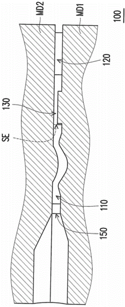
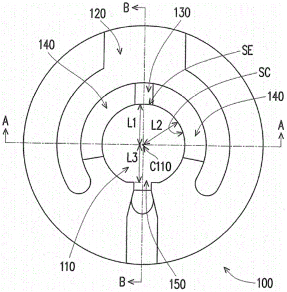
[0057] figure 1 is a schematic side view of a mold for forming lenses according to an embodiment of the present invention. Figure 2A yes figure 1 The top view of the mold cavity. Please refer to Figure 1 to Figure 2A , the mold 100 for forming a lens in this embodiment includes a mold cavity 110 , an exhaust cavity 120 , a first exhaust channel 130 , at least one second exhaust channel 140 and a filling hole 150 . For example, if figure 1As shown, in this embodiment, the mold 100 includes a first mold MD1 and a second mold MD2, and a mold cavity 110, an exhaust cavity 120, and a first exhaust passage are formed between the first mold MD1 and the second mold MD2. 130 and at least one second exhaust channel 140 .

[0058] Further, if Figure 2A As shown, the mold 100 has an air escape section SE and at least one arc inner surface SC to define a mold cavity 110 . On the other hand, in this embodiment, the injection hole 150 communicates with the mold cavity 110 , and is ...


PUM


Abstract

The invention provides a die for forming a lens, a lens, and a method for manufacturing a lens. The die for forming a lens includes a die cavity, an exhaust cavity, a first exhaust channel, and at least one second exhaust channel. The exhaust cavity is positioned at the periphery of the die cavity. The first exhaust channel is communicated with the exhaust cavity and the die cavity, and has a first depth. The second exhaust channel is communicated with the exhaust cavity and the die cavity, and has a second depth. The first depth is different from the second depth. Moreover, the lens and the method for manufacturing a lens are disclosed.

Description

technical field [0001] The invention relates to a mold for forming a lens, a lens and a manufacturing method of the lens. Background technique [0002] In recent years, with the development of electronic products towards light, thin, short, and small, the length of the lenses configured on electronic products (such as mobile phones with camera functions) has also been reduced, so the upper lens also has a relatively thin thickness. However, when the thin lens is molded, it is easy to cause the problem of poor molding. [0003] In detail, the mold cavity structure for forming a lens usually includes a central optical active area and a surrounding non-optical active area. When the liquid resin material used to make the lens is injected into the mold cavity, it will flow in a smooth wave around the mold cavity, but due to the gap around the mold cavity and the center of the mold cavity, when the resin material is injected into the center of the mold cavity, there will be The...

Claims


Application Information

Patent Timeline
Patent Type & Authority Applications(China)
IPC IPC(8): B29C33/10B29D11/00G02B3/00
Inventor 陈淑萱庄万枝田明代
Owner E PIN OPTICAL IND
Learn More