A reversible rotating electromagnet device

A technology of rotating electromagnets and electromagnets, applied in the field of electromagnets, can solve problems such as inability to meet

Active Publication Date: 2016-09-21
TSE TECH NINGBO
View PDF9 Cites 0 Cited by
  • Summary
  • Abstract
  • Description
  • Claims
  • Application Information

AI Technical Summary

Problems solved by technology

Because the usual rotating electromagnet can only achieve one-way rotation, it cannot meet the needs of existing products

Method used


Image

  • A reversible rotating electromagnet device
  • A reversible rotating electromagnet device

Examples


Embodiment Construction

[0012] Below in conjunction with specific embodiment, further illustrate the present invention. It should be understood that these examples are only used to illustrate the present invention and are not intended to limit the scope of the present invention. In addition, it should be understood that after reading the teachings of the present invention, those skilled in the art can make various changes or modifications to the present invention, and these equivalent forms also fall within the scope defined by the appended claims of the present application.

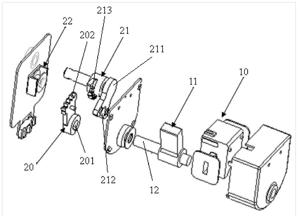
[0013] Embodiments of the present invention relate to a reversible rotating electromagnet arrangement such as figure 1 and figure 2 As shown, it includes a two-way electromagnet and a reversing mechanism, and the reversing mechanism includes a connecting rod 20 for transmitting the output torque of the two-way electromagnet, an output shaft 21 connected with the connecting rod 20, and a switch for realizing the switching posi...


PUM


Abstract

The invention relates to a reversible rotary electromagnet device. The reversible rotary electromagnet device comprises a bidirectional electromagnet and a reversing mechanism, wherein the reversing mechanism comprises a connection rod for transmitting output torsion of the bidirectional electromagnet, an output shaft connected with the connection rod, and a keeping electromagnet for realizing a switching position; the keeping electromagnet is used for drawing the connection rod after being electrified so that the connection rod is separated from the output shaft to realize angle switching of the output shaft. With the adoption of the reversible rotary electromagnet device, the steering of the output shaft in two positions can be realized.

Description

technical field [0001] The invention relates to an electromagnet, in particular to a reversible rotating electromagnet device. Background technique [0002] A conductive winding matching its power is wound on the outside of the iron core. This current-carrying coil is magnetic like a magnet, and it is also called an electromagnet. In the prior art, the electromagnet is usually made into a bar shape or a hoof shape to make the iron core easier to magnetize. In addition, in order to demagnetize the electromagnet immediately when it is powered off, it is often made of soft iron or silicon steel materials that demagnetize faster. Such an electromagnet is magnetic when energized, and the magnetism disappears when the power is turned off. Because the usual rotating electromagnet can only realize one-way rotation, it cannot meet the needs of existing products. Contents of the invention [0003] The technical problem to be solved by the present invention is to provide a reversi...

Claims


Application Information

Patent Timeline
Patent Type & Authority Patents(China)
IPC IPC(8): H01F7/08H01F7/121
Inventor 林柳叶
Owner TSE TECH NINGBO
Why Eureka
Try Eureka