
Regulator for power generator

A technology for regulators and generators, applied in the direction of controlling generators, generator control parts, electrical components, etc., can solve the problems of increasing the cost of regulators and the difficulty of spare parts management, and achieve the effect of meeting installation needs

Active Publication Date: 2015-05-20
索恩格汽车部件(中国)有限公司
View PDF4 Cites 0 Cited by
  • Summary
  • Abstract
  • Description
  • Claims
  • Application Information

AI Technical Summary

Problems solved by technology

This inevitably increases the cost of the regulator and the difficulty of managing spare parts

Method used


Image

  • Regulator for power generator
  • Regulator for power generator
  • Regulator for power generator

Examples


Embodiment Construction

[0032] The preferred embodiments of the present invention will be described in detail below with reference to examples. Those skilled in the art should understand that these exemplary embodiments do not imply any limitation to the present invention.

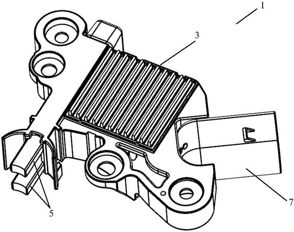
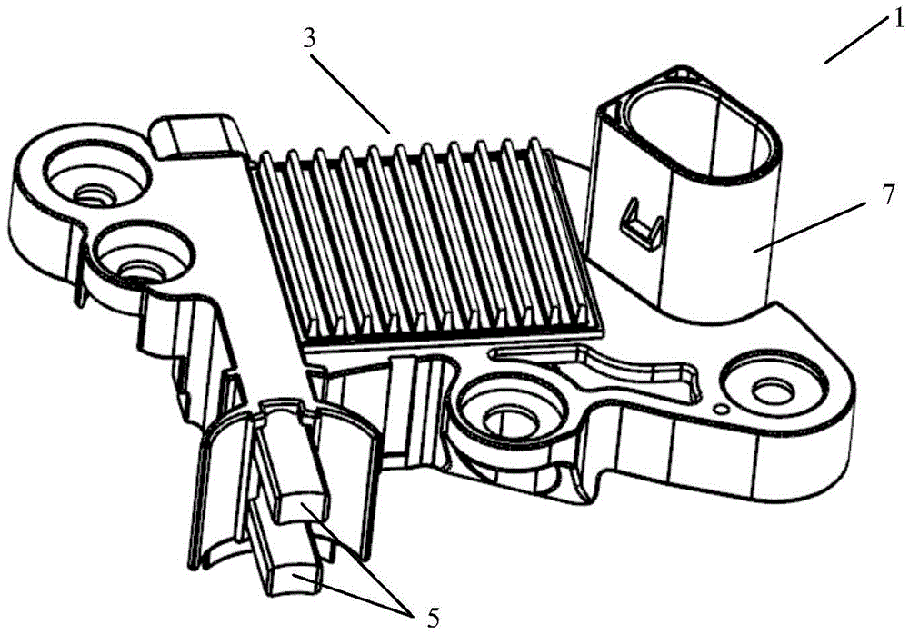
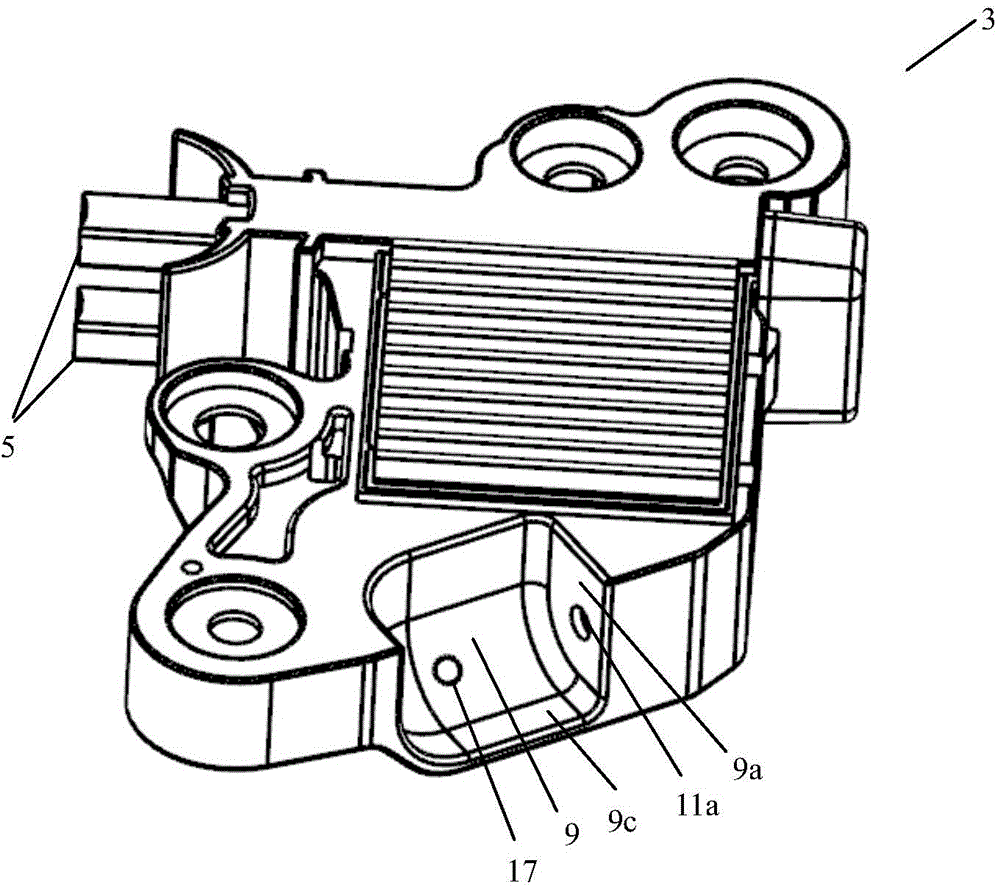
[0033] figure 1 is a perspective view of a regulator for a generator according to a preferred embodiment of the present invention. figure 2 is another perspective view of a regulator for a generator according to a preferred embodiment of the present invention, wherein the connector of the regulator is in the same position as figure 1 in different orientations. Such as figure 1 with 2 As shown, a regulator 1 for a generator according to a preferred embodiment of the present invention includes a main body 3, a carbon brush 5 extending from the main body 3 and used to connect with the generator, and a control device for connecting with a vehicle through a cable The unit (not shown) is connected to the connector 7.

[0034] Un...


PUM


Abstract

The invention provides a regulator for a power generator. The regulator comprises a main body part and a connector connected with a matched joint of a cable, wherein the connector is an independent part separated from the main body part and is pivotally arranged on the main body part. The connector can be turned in relative to the main body part to the needed direction so as to meet different mounting demands of the power generator and the regulator, and thus universality is provided.

Description

technical field [0001] The present invention relates to generators, and more particularly to a regulator for generators. Background technique [0002] Vehicles, such as vehicles, ships, and aircrafts, usually need to be equipped with generators to supply power to the vehicles or to charge accumulators mounted on the vehicles. The generator is usually driven by the engine, and its speed is also determined by the engine speed. During the normal running of the vehicle, the engine speed varies widely, which will inevitably have a great impact on the output voltage of the generator. In order to ensure that the generator output voltage is in a specific range, a regulator needs to be set for the generator. The regulator can adjust the excitation current of the generator according to the change of the engine speed, so that the output voltage of the generator can be kept relatively constant. For this, the regulator needs to be connected to the generator as well as to the control u...

Claims


Application Information

Patent Timeline
IPC IPC(8): H02P9/02
CPCH02P9/02H02P9/48
Inventor 方刚曾宪波戴洪波
Owner 索恩格汽车部件(中国)有限公司
Learn More