Rotor sheath of high-speed permanent magnet motor

A technology of rotor sheath and permanent magnet motor, applied in the direction of magnetic circuit rotating parts, magnetic circuit shape/style/structure, etc., can solve the problems of rotor side permanent magnet demagnetization, rotor temperature rise, large eddy current loss, etc. Achieve the effect of reducing heat generation, improving working performance and reducing rotor loss

Inactive Publication Date: 2015-05-20
ZHEJIANG UNIV
View PDF3 Cites 6 Cited by
  • Summary
  • Abstract
  • Description
  • Claims
  • Application Information

AI Technical Summary

Problems solved by technology

[0006] In order to solve the problems of the existing high-speed permanent magnet motor rotor side with a sheath, the eddy current loss is too high and the rotor temperature rises too high, causing the permanent magnet on the rotor side to lose magnetism, etc., the present invention designs a high-speed permanent magnet motor rotor sheath

Method used


Image

  • Rotor sheath of high-speed permanent magnet motor

Examples


Embodiment Construction

[0018] The preferred embodiments of the present invention will be described in detail below in conjunction with the accompanying drawings, so that the advantages and features of the present invention can be more easily understood by those skilled in the art, so as to define the protection scope of the present invention more clearly.

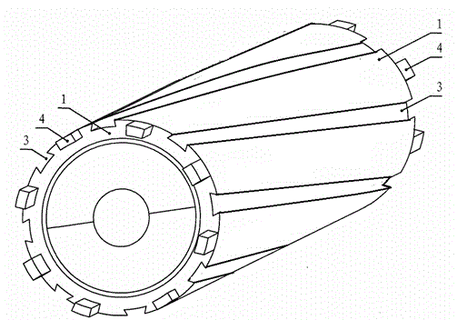
[0019] see figure 1 , The embodiment of the present invention includes: a high-speed permanent magnet motor rotor sheath, which is a cylindrical structure, including: a sheath sleeve 1; a rotating groove 3;

[0020] The rotary grooves 3 are evenly distributed on the outer surface of the rotor sheath 1;

[0021] The protruding blocks 4 are uniformly fixed on both end surfaces of the sheath sleeve 1 .

[0022] The cross-section of the rotary grooves 3 is isosceles trapezoidal, and each rotary groove 3 is parallel distributed on the outer surface of the sheath sleeve 1 . The rotary groove 3 is arc-shaped. The sheath includes a plurality of protru...


PUM


Abstract

The invention discloses a rotor sheath of a high-speed permanent magnet motor, relates to a structure of a rotor of the high-speed permanent magnet motor, belongs to the field of the motor, and aims to solve the problem that eddy-current loss is increased by arranging the sheath on the rotor side of the existing high-speed permanent magnet motor to cause temperature rise of the rotor and further cause demagnetization of a permanent magnet in the rotor so as to damage the motor body. The rotor sheath of the high-speed permanent magnet motor comprises a rotor sheath cylinder, and is characterized in that a plurality of rotary grooves are uniformly distributed around the outer surface of the rotor sheath cylinder. According to the rotor sheath of the high-speed permanent magnet motor, a plurality of convex blocks are uniformly and fixedly arranged on the two end faces of the sheath cylinder. The rotor sheath is suitable for improving the rotor sheath of the high-speed permanent magnet motor in service in existing industries, and meanwhile suitable for reproducing and machining the high-speed permanent magnet motor.

Description

technical field [0001] The invention relates to the field of motors, in particular to a rotor sheath of a high-speed permanent magnet motor. Background technique [0002] Surface-mounted high-speed permanent magnet brushless motors often have a layer of high-strength non-magnetic sheath outside the permanent magnet to protect the high-speed rotating permanent magnet. The sheath can be metal, such as stainless steel, titanium alloy, nickel alloy, etc., or non-metallic material, such as glass fiber, carbon fiber, etc. The electrical conductivity of the metal sheath is large, and a large eddy current loss will be generated in the sheath, while the electrical conductivity of the non-metallic material is low, and the eddy current loss is relatively small. At the same time, since the eddy current of the protective sheath has a shielding effect on the magnetic field of the permanent magnet and the rotating shaft, the eddy current loss of the permanent magnet of the rotor and th...

Claims


Application Information

Patent Timeline
Patent Type & Authority Applications(China)
IPC IPC(8): H02K1/22H02K1/32
CPCH02K1/27H02K1/32
Inventor 陈善恩沈红
Owner ZHEJIANG UNIV
Why Eureka
Try Eureka