A quick-change interface for manipulator joints that can be replaced on rail
A technology of manipulator and interface replacement, which is applied in the field of aerospace, can solve the problems of large-scale space manipulators, in-orbit maintenance, etc., and achieve the effect of large tolerance capability, low tolerance requirements, and reliable locking
- Summary
- Abstract
- Description
- Claims
- Application Information
AI Technical Summary
Problems solved by technology
Method used
Image
Examples
specific Embodiment approach 1
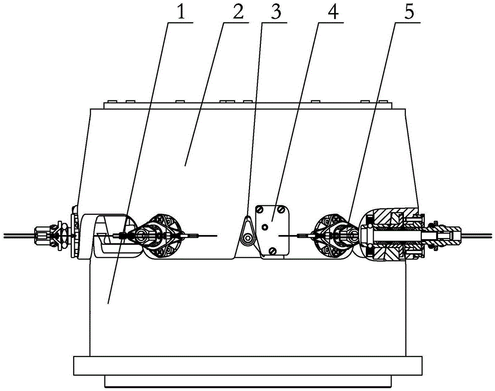
[0009] Specific implementation mode one: combine Figure 1 to Figure 10 Describe the present embodiment. The on-rail replaceable mechanical arm joint quick-change interface described in this embodiment includes a convex body 1, a concave body 2 matching with the convex body, a guide mechanism 3, a positioning mechanism 4, an electrical connector auxiliary The connection mechanism and six quick-disconnect connection mechanisms 5, the positioning mechanism 4, and the auxiliary connection mechanism of the electrical connector are installed on the concave body 2, the guide mechanism 3 is installed on the convex body 1, and the six quick-disconnect connection mechanisms 5 are installed evenly On the female body 2 , the female body 2 is connected to the male body 1 through six quick-disconnect connection mechanisms 5 .
specific Embodiment approach 2
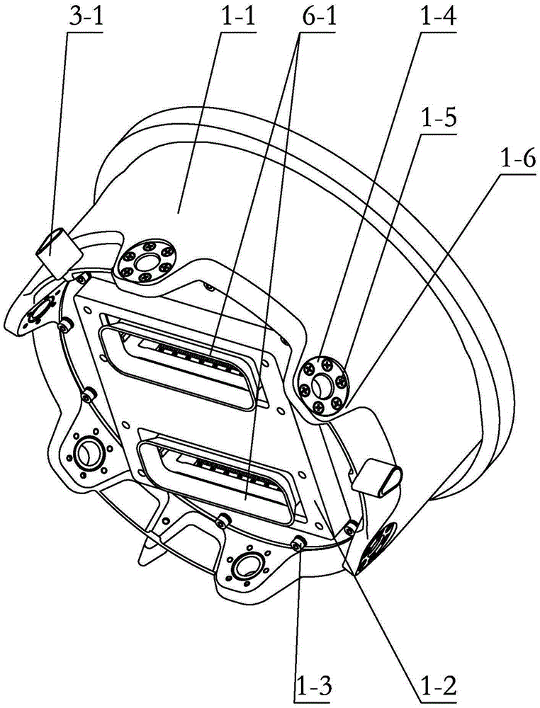
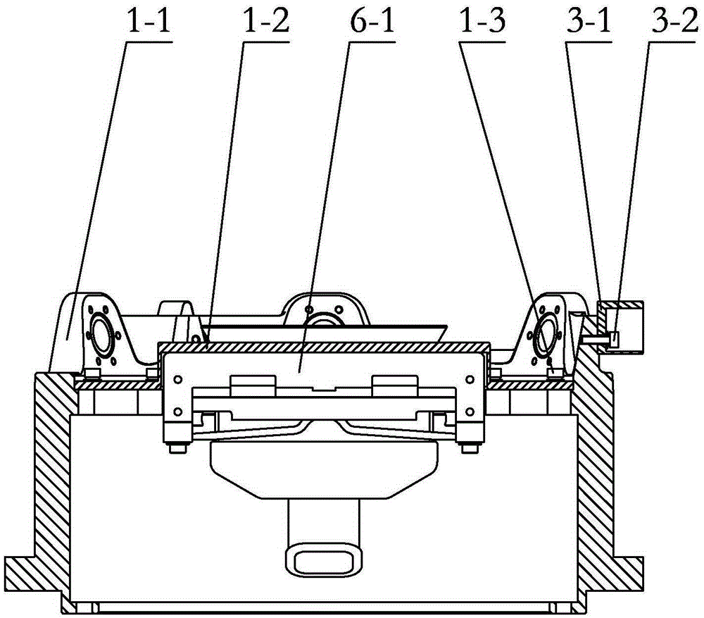
[0010] Specific implementation mode two: combination Figure 1 to Figure 4 Describe this embodiment, the convex body 1 of the on-rail replaceable mechanical arm joint quick-change interface described in this embodiment includes a convex body shell 1-1, a first electrical connector positioning plate 1-2, and six expansion pins Set 1-4, a plurality of first connecting screws 1-3 and a plurality of second connecting screws 1-5, the first electrical connector positioning plate 1-2 is installed side by side on the convex body through a plurality of first connecting screws 1-3 Inside the casing 1-1, six lugs 1-6 are evenly distributed along the circumferential direction on the lower surface of the convex body casing 1-1, and each lug 1-6 is respectively inserted with an expansion pin sleeve 1-4, each Each expansion pin sleeve 1-4 is fixedly connected with the lug 1-6 through a plurality of second connecting screws 1-5.
[0011] The technical effect of this embodiment is: such arran...
specific Embodiment approach 3
[0012] Specific implementation mode three: combination Figure 5 and Figure 6 Describe this embodiment. The concave body 2 of the on-rail replaceable mechanical arm joint quick-change interface in this embodiment includes a concave body shell 2-1, a bottom plate 2-7, and six outer ring expansion pin sleeves 2-3. , six inner ring expansion pin sleeves 2-5, a plurality of third connecting screws 2-2, a plurality of fourth connecting screws 2-4 and a plurality of fifth connecting screws 2-8, the outer shell of the concave body shell 2-1 Six outer ear plates 2-1-1 are evenly distributed along the circumferential direction on the ring, and six inner ear plates 2-1-2 are evenly distributed along the circumferential direction on the inner ring of the concave body shell 2-1, and each outer ear plate 2- 1-1 and an inner ear plate 2-1-2 form a pair of locking ear plates, each lug 1-6 on the convex body 1 can be inserted into a pair of said locking ear plates correspondingly, each oute...
PUM
 Abstract
Description
Claims
Application Information
 - R&D Engineer
- R&D Manager
- IP Professional
- Industry Leading Data Capabilities
- Powerful AI technology
- Patent DNA Extraction
Browse by: Latest US Patents, China's latest patents, Technical Efficacy Thesaurus, Application Domain, Technology Topic, Popular Technical Reports.
© 2024 PatSnap. All rights reserved.Legal|Privacy policy|Modern Slavery Act Transparency Statement|Sitemap|About US| Contact US: help@patsnap.com


