Automatic water changing structure

An automatic, water outlet valve technology, applied in fish farming, application, animal husbandry, etc., can solve problems such as affecting fish growth and unclean water

Inactive Publication Date: 2015-05-20
SHAANXI JOIN CREATE SCI & TECH
View PDF0 Cites 0 Cited by
  • Summary
  • Abstract
  • Description
  • Claims
  • Application Information

AI Technical Summary

Problems solved by technology

[0002] At present, if there is no one in the house for a long time, the water in the fish tank will not be replaced, and the water will be unclean, which will affect the growth of fish

Method used


Image

  • Automatic water changing structure

Examples


Embodiment Construction

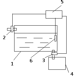
[0009] The present invention will be described in detail below in conjunction with the accompanying drawings.

[0010] With reference to accompanying drawing, a kind of automatic water changing structure comprises fish tank 1, and fish tank 1 is provided with water inlet valve 2 and water outlet valve 3, and the lower end of water outlet valve 3 is provided with water collecting tank 4, and the control end of water inlet valve 2 and water outlet valve 3 They are respectively connected to the output of the controller 5, and the output of the water quality analyzer 6 is connected to the input of the controller 5.

[0011] Working principle of the present invention:

[0012] The controller 5 controls the water inlet valve 2 and the water outlet valve 3 to open or close according to the water quality measured by the water quality measuring instrument 6, and the water discharged by the water outlet valve 3 is collected in the water collection tank 4, thereby realizing the aut...


PUM


Abstract

An automatic water changing structure comprises a fish tank. The fish tank is provided with a water inlet valve and a water outlet valve, a water collecting tank is arranged at the lower end of the water outlet valve, the control end of the water inlet valve and the control end of the water outlet valve are connected with output of a controller, and output of a water quality determinator is connected with input of the controller. The controller controls the water inlet valve and the water outlet valve to be opened or closed according to the water quality conditions measured by the water quality determinator, water drained by the water outlet valve is collected in the water collecting tank, and therefore automatic water changing for the fish tank is achieved.

Description

technical field [0001] The invention relates to an automatic water changing structure. Background technique [0002] Now, if there is no one in the family for a long time and no one changes the water in the fish tank, the water will not be clean and the growth of fish will be affected. Contents of the invention [0003] In order to overcome the defects of the above-mentioned prior art, the object of the present invention is to provide an automatic water change structure, which can automatically change water for fish tanks. [0004] In order to achieve the above object, technical scheme of the present invention is: [0005] An automatic water exchange structure, comprising a fish tank 1, the fish tank 1 is provided with a water inlet valve 2 and a water outlet valve 3, the lower end of the water outlet valve 3 is provided with a water collection tank 4, and the control ends of the water inlet valve 2 and the water outlet valve 3 are respectively connected with the cont...

Claims


Application Information

Patent Timeline
Patent Type & Authority Applications(China)
IPC IPC(8): A01K63/04
CPCA01K63/04A01K63/003
Inventor 不公告发明人
Owner SHAANXI JOIN CREATE SCI & TECH
Why Eureka
Try Eureka