A friction and wear testing machine with improved structure

A friction and wear test and improved structure technology, applied in the mechanical field, can solve problems such as large errors in test data, troublesome test data analysis, and inability to fix materials accurately, so as to achieve the effect of reducing pressure

Inactive Publication Date: 2017-12-12
HUBEI HONGLI HYDRAULIC TECH CO LTD
View PDF10 Cites 0 Cited by
  • Summary
  • Abstract
  • Description
  • Claims
  • Application Information

AI Technical Summary

Problems solved by technology

[0003] When conducting friction and wear tests on materials, there are mainly the following two problems. One is that the materials cannot be accurately fixed on the test platform, so there are large errors in the test data; the other is that the load applied to the materials cannot be set to a constant value. If the load cannot become an invariant, it will cause great trouble in the analysis of test data

Method used


Image

  • A friction and wear testing machine with improved structure
  • A friction and wear testing machine with improved structure
  • A friction and wear testing machine with improved structure

Examples


Embodiment Construction

[0023] The following are specific embodiments of the present invention and in conjunction with the accompanying drawings, the technical solutions of the present invention are further described, but the present invention is not limited to these embodiments.

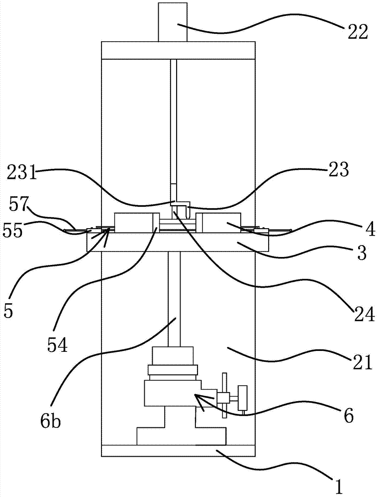
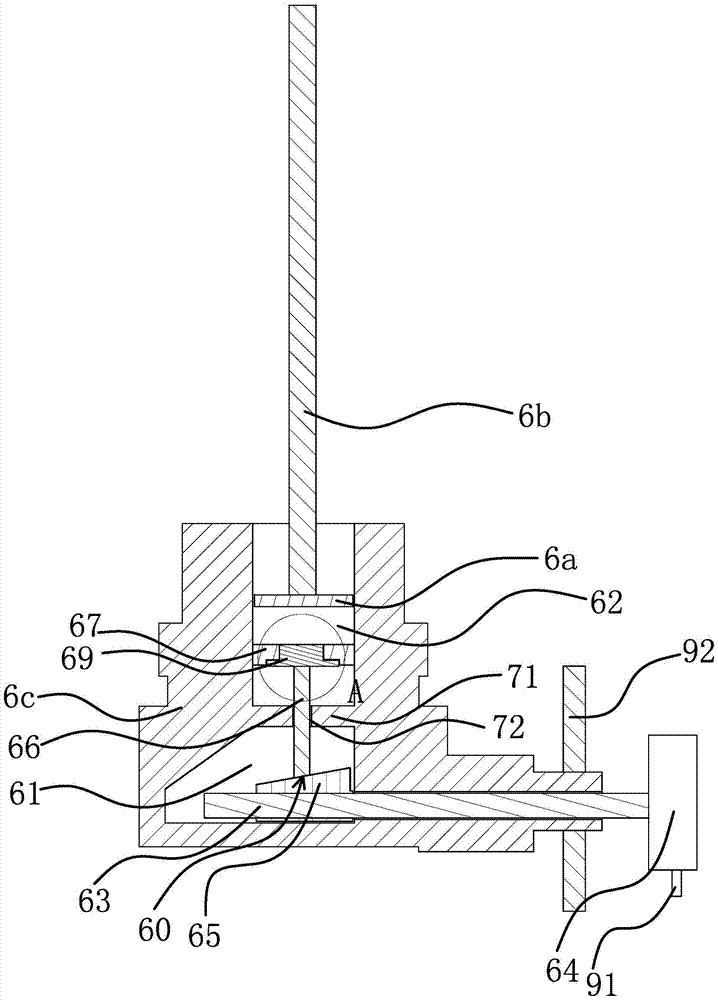
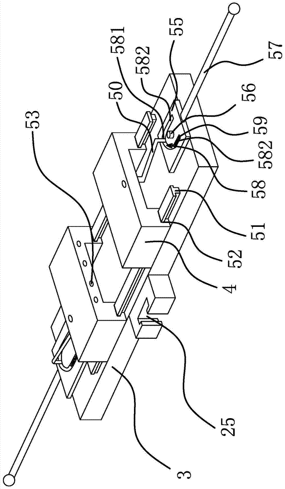
[0024] Such as figure 1 , figure 2 and image 3 As shown, a friction and wear testing machine with an improved structure includes a base 1, a support panel 21 is fixedly arranged on the base 1, a drive motor 22 is arranged on the upper end of the support panel 21, and a stop is fixed on the output shaft of the drive motor 22. Lean against the indenter 23 on the upper surface of the workpiece, and the support panel 21 is provided with a slide rail-24. 25. The clamping base plate 3 is slidably connected to the support panel 21. Two mutually parallel clamping blocks 4 are slidingly connected to the clamping base plate 3. The clamping base plate 3 is provided with a The locking structure 5, the lower end of the base 1 is p...


PUM


Abstract

The invention provides a friction-wear testing machine with an improved structure, belongs to the technical field of machinery, and solves the technical problems of inaccuracy of testing and the like due to the fact that a conventional friction-wear testing machine cannot better clamp a workpiece. The friction-wear testing machine with the improved structure comprises a base, wherein a support panel is fixedly arranged on the base, a drive motor is arranged at the upper end of the support panel, a press head propped against the upper surface of the workpiece is fixedly arranged on an output shaft of the drive motor, and a slide track I is arranged on the support panel; the testing machine further comprises a clamping substrate, a chute I matched with the slide track I is formed in the clamping substrate, the clamping substrate is glidingly connected to the support panel, two parallel clamping blocks are glidingly connected to the clamping substrate, locking structures which can fix the clamping blocks on the clamping substrate are arranged on the clamping substrate, a loading oil cylinder is arranged at the lower end of the base, and the end part of a piston rod of the loading oil cylinder is fixedly connected with the clamping substrate. The friction-wear testing machine has the advantages of workpiece fixing firmness, accurate testing and the like.

Description

technical field [0001] The invention belongs to the technical field of machinery and relates to a friction and wear testing machine with an improved structure. Background technique [0002] The process route adopted for permeating Ti(CN) is based on the successful preparation of TiC permeating layer. When discussing and studying the process parameters of double-glow permeating TiC and Ti(CN), through comparative analysis of each The thickness and surface hardness of the permeated coating obtained by the group test are used to determine the optimized process parameters for preparing TiC and Ti(CN) permeated coatings, and then a friction and wear testing machine is needed. The surface is rubbed, and its wear condition is detected within the predetermined time, predetermined friction intensity and specified load, so as to obtain the process parameters such as the friction resistance strength of the material surface. [0003] When conducting friction and wear tests on materials...

Claims


Application Information

Patent Timeline
Patent Type & Authority Patents(China)
IPC IPC(8): G01N3/56
Inventor 徐景丽
Owner HUBEI HONGLI HYDRAULIC TECH CO LTD
Why Eureka
Try Eureka