Double-sleeve

A double-sleeve and outer-pipe technology, applied in the field of double-sleeves, can solve the problems of low mixing concentration, easy to block the pipeline, and increase the maintenance amount, and achieve the effect of speeding up material transportation, ensuring effectiveness, and improving production efficiency.

Inactive Publication Date: 2015-05-13
JIANGSU JIUSHENG ENVIRONMENTAL PROTECTION EQUIP
View PDF6 Cites 6 Cited by
  • Summary
  • Abstract
  • Description
  • Claims
  • Application Information

AI Technical Summary

Problems solved by technology

[0002] The pneumatic material conveying device is mainly composed of two parts: a conveying pump and a conveying pipeline. For a long time in the past, most of the devices for pneumatically conveying materials used a single-pipe conveying device. During the conveying process, when the mixing concentration is high, it is easy to block the pipeline. The mixing concentration is low, the air consumption increases, the wind speed is too fast, the pipeline wears seriously, wastes energy, and increases the amount of maintenance
In the prior art, the internal bypass pipe is installed on the inner wall of the main conveying pipe, so that the auxiliary airflow can generate enough deflecting airflow in the conveying pipe, so that the stagnant material blocked in the conveying pipe is brought up by the turbulent flow, and continues to flow along the material. The flow direction is transported, thereby avoiding the blockage of the pipeline, reducing the gas consumption, saving energy, reducing the wear and tear of the pipeline, and reducing the maintenance cost of the pipeline. Passing through the pipe, due to the action of air flow, there will often be a small amount of material deposition at the bottom of the outer pipe. Long-term use will cause deposition at the bottom of the pipe, which is prone to blockage and reduces the efficiency of material delivery.

Method used


Image

  • Double-sleeve
  • Double-sleeve

Examples


Embodiment

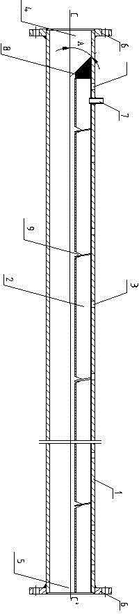
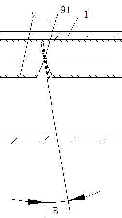
[0018] As shown in the figure, a double casing includes an outer tube 1 and an inner tube 2, wherein both the outer tube 1 and the inner tube 2 have a circular structure, and the top of the outer tube 1 is provided with 8 welding holes 3 , the welding holes 3 are distributed in a straight line, the inner pipe 2 is located at the top of the outer pipe 1, and the inner pipe 2 is welded on the inner wall of the outer pipe 1 through the welding holes 3; one end of the double casing is an inlet end 4, one end is an outlet end 5, and the two ends are provided with a fixed ring 6, and the fixed ring 6 is fastened to the outside of the outer tube 1; the outer top of the double casing is provided with an air inlet pipe 7, and the The air inlet pipe 7 runs through the wall of the outer pipe 1, the bottom of the air inlet pipe 7 is connected to the inside of the inner pipe 2, and one end of the inner pipe 2 is provided with a sealing head 8, which is close to the inlet end 4, and the seal...


PUM


Abstract

The invention discloses a double-sleeve. The double-sleeve comprises an outer pipe and an inner pipe. The top of the outer pipe is provided with a plurality of welding holes. The welding holes are distributed in a linear mode, and the inner pipe is located at the top end in the outer pipe. The inner pipe is welded to the inner wall of the outer pipe through the welding holes. One end of the double-sleeve is the inlet end, the other end of the double-sleeve is the outlet end, both the two ends are provided with fixing rings, and the fixing rings are fastened outside the outer pipe. The outer top end of the double-sleeve is provided with an air inlet pipe. The air inlet pipe penetrates through the pipe wall of the outer pipe. The bottom of the air inlet pipe is connected into the inner pipe. One end of the inner pipe is provided with an end socket. The end socket is close to the inlet end. The section of the end socket is of a trapezoidal structure, and the inclined edge of the section of the end socket and the central axis of the outer pipe form an inclined angle of 45 degrees with the section of the double-sleeve as the datum plane. The bottom of the inner pipe is provided with a plurality of openings, the section of the openings is of a triangular structure, air guide plates are arranged on the openings and obliquely arranged, and the slant angle between the air guide plates and the vertical direction is 10 degrees. By means of the double-sleeve, material deposition at the bottom of the double-sleeve can be avoided effectively, material conveying efficiency is improved, and the use effect is improved.

Description

technical field [0001] The invention relates to a double casing and belongs to the field of pneumatic conveying systems. Background technique [0002] The pneumatic material conveying device is mainly composed of two parts: a conveying pump and a conveying pipeline. For a long time in the past, most of the devices for pneumatically conveying materials used a single-pipe conveying device. During the conveying process, when the mixing concentration is high, it is easy to block the pipeline. When the mixing concentration is low, the air consumption increases, the wind speed is too fast, the pipeline wears seriously, wastes energy, and increases the amount of maintenance. In the prior art, the internal bypass pipe is installed on the inner wall of the main conveying pipe, so that the auxiliary airflow can generate enough deflecting airflow in the conveying pipe, so that the stagnant material blocked in the conveying pipe is brought up by the turbulent flow, and continues to flow...

Claims


Application Information

Patent Timeline
IPC IPC(8): B65G53/52
Inventor 薛平
Owner JIANGSU JIUSHENG ENVIRONMENTAL PROTECTION EQUIP
Why Eureka
Try Eureka