
Welding tool applied to suspension installation assembly

A welding tooling and assembly technology, applied in welding equipment, auxiliary welding equipment, welding/cutting auxiliary equipment, etc., can solve problems affecting accuracy, a large number of manpower, difficulties, etc., and achieve the goal of improving work efficiency, stable positioning, and precise positioning Effect

Inactive Publication Date: 2015-05-13
力帆科技(集团)股份有限公司
View PDF6 Cites 9 Cited by
  • Summary
  • Abstract
  • Description
  • Claims
  • Application Information

AI Technical Summary

Problems solved by technology

Because the usable space of the suspension installation assembly is small, the welding of the suspension installation assembly in the past generally uses a hand-held tool for positioning and clamping. Since the suspension has three walls, namely the rear wall and the two side walls connected to the two ends of the rear wall , the three walls are irregular curved surfaces, it is very difficult to fix all three walls of the suspension, and it will affect the accuracy
[0003] When using hand-held tooling for positioning and clamping, the positioning pins at both ends must enter the two positioning holes of the suspension installation assembly at the same time. Due to the welding error of the previous sequence, the tolerance of the parts, and the overlap with the longitudinal beam, it is difficult for the worker to operate. It has brought great difficulties. This process will take a lot of time and a lot of manpower during production.
[0004] When using hand-held tooling to open, due to the complex structure here, the longitudinal beams need to be welded, and it is impossible to design a large mechanism, resulting in very laborious and time-consuming opening.

Method used


Image

  • Welding tool applied to suspension installation assembly
  • Welding tool applied to suspension installation assembly
  • Welding tool applied to suspension installation assembly

Examples


Embodiment Construction

[0022] The following will clearly and completely describe the technical solutions in the embodiments of the present invention with reference to the accompanying drawings in the embodiments of the present invention. Obviously, the described embodiments are only some, not all, embodiments of the present invention. Based on the embodiments of the present invention, all other embodiments obtained by persons of ordinary skill in the art without making creative efforts belong to the protection scope of the present invention.

[0023] First of all, before describing the embodiments, it is necessary to explain some terms appearing in this text. E.g:

[0024] Herein, terms such as "first" and "second" may be used to describe various elements, but these elements should not be limited by these terms. These terms are only used to distinguish one element from another. Thus, a "first" element could also be termed a "second" element without departing from the teachings of the present inven...


PUM


Abstract

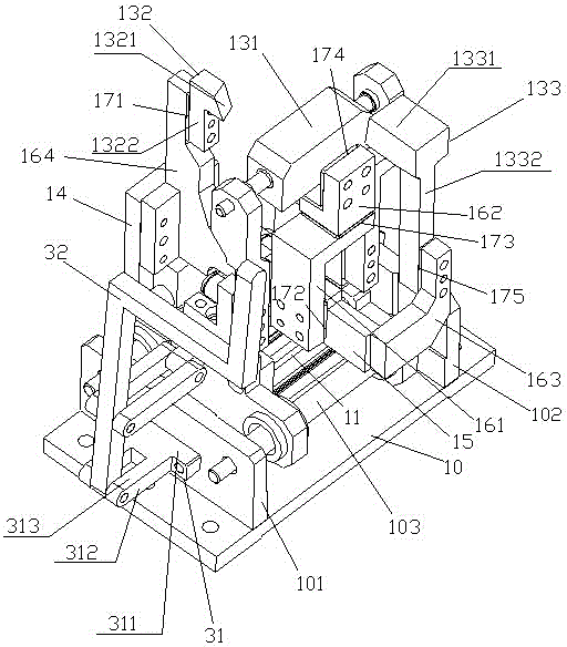
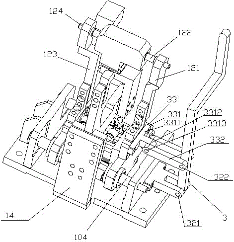
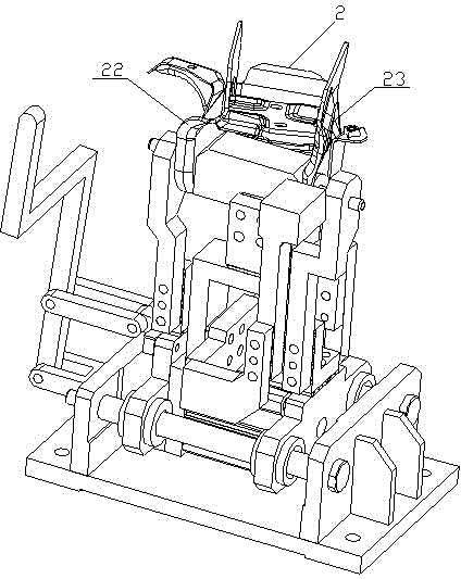
The invention discloses a welding tool applied to a suspension installation assembly. The welding tool applied to the suspension installation assembly comprises a substrate, a first fixing plate, a second fixing plate, two shafts, an air cylinder, a first positioning block, a second positioning block, a first positioning pin, a second positioning pin, a first limiting block, a second limiting block and a third limiting block, wherein the first fixing plate and the second fixing plate are arranged on two sides of the substrate oppositely, the two shafts are arranged between the first fixing plate and the second fixing plate, the air cylinder is arranged in the middle of a rectangular frame, the first positioning block and the second positioning block are arranged at two ends of the air cylinder and connected with the two shafts in a sliding mode, the first positioning pin and the second positioning pin are arranged at the upper ends of the first positioning block and the second positioning block respectively, the first limiting block is located between the first positioning pin and the second positioning pin, the second limiting block is arranged at the back of the first limiting block, and the third limiting block is arranged in front of the first limiting block and near the second positioning pin. The welding tool applied to the suspension installation assembly enables a worker to conveniently and rapidly position a suspension, shortens the welding time and improves welding efficiency.

Description

technical field [0001] The invention relates to a welding tool, in particular to a welding tool used for a suspension installation assembly. Background technique [0002] The welding positioning of the suspension mounting assembly has always been a difficult problem. It needs to ensure accurate positioning and simple and quick operation. Because the usable space of the suspension installation assembly is small, the welding of the suspension installation assembly in the past generally uses a hand-held tool for positioning and clamping. Since the suspension has three walls, namely the rear wall and the two side walls connected to the two ends of the rear wall , the three walls are irregular curved surface shape, it is very difficult to fix the three walls of the suspension, and it will affect the accuracy. [0003] When using hand-held tooling for positioning and clamping, the positioning pins at both ends must enter the two positioning holes of the suspension installation ...

Claims


Application Information

Patent Timeline
Patent Type & Authority Applications(China)
IPC IPC(8): B23K37/04
CPCB23K37/0443B23K2101/006
Inventor 王权余桃罗垚
Owner 力帆科技(集团)股份有限公司
Learn More