
Liquid pumping method from container

A container and liquid technology, which is applied to table utensils, home utensils, table utensils, etc., can solve problems such as laboriousness, reduced air pressure, and difficulty in absorbing clean liquids, and achieve smooth liquid absorption, high efficiency, and avoid pressure differences.

Inactive Publication Date: 2015-05-13
CENTRAL SOUTH UNIVERSITY OF FORESTRY AND TECHNOLOGY
View PDF5 Cites 0 Cited by
  • Summary
  • Abstract
  • Description
  • Claims
  • Application Information

AI Technical Summary

Problems solved by technology

[0002] In the process of sucking liquid from a closed container, such as sucking oil (non-volatile oil, such as peanut oil, etc.) There is no conduction at the suction hole. Therefore, in the process of absorbing liquid, as the liquid in the container decreases, the air pressure in the container decreases, forming a pressure difference with the outside, and it is difficult to suck the liquid in the container clean, or Drawing up liquids can be laborious, so it is necessary to devise a way to draw liquids from containers

Method used


Image

  • Liquid pumping method from container
  • Liquid pumping method from container
  • Liquid pumping method from container

Examples


Embodiment 1

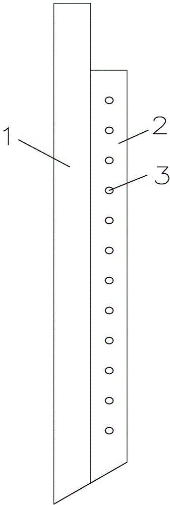
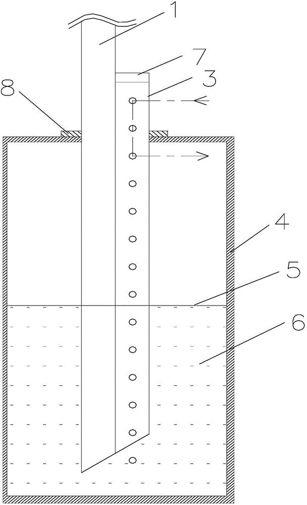
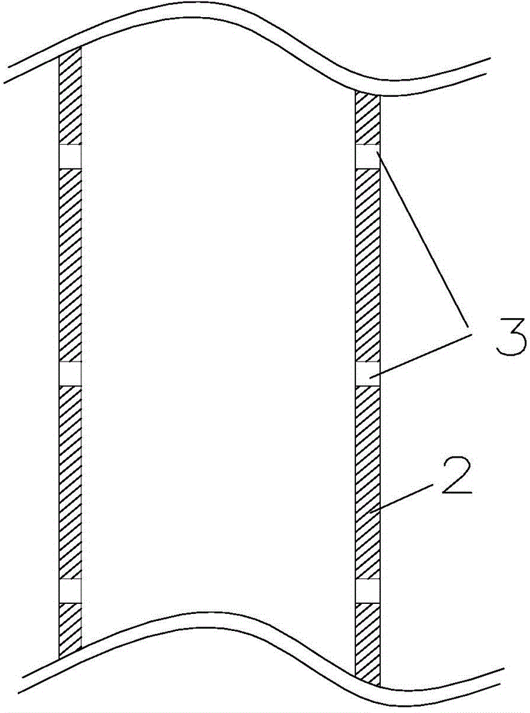
[0040] Embodiment 1: as Figure 1-3 , a method for sucking liquid from a container, the container is an oil barrel; a compound anti-blocking suction pipe is inserted in the through hole of the top cover of the container 4, and the lower end of the compound anti-blocking suction pipe goes deep into the container Below the liquid level, the composite anti-blocking suction pipe includes a main pipe 1 and a secondary pipe 2 connected side by side; the wall of the secondary pipe is provided with a plurality of ventilation holes 3 along the axial direction of the secondary pipe; At least one vent hole is provided between the top cover and the first vent hole, and at least one vent hole is provided between the top cover and the secondary pipe nozzle, which is recorded as the second vent hole; The air inside and outside the container can be communicated through the first air hole and the second air hole, so that the liquid can be sucked out of the container more conveniently through t...

Embodiment 2

[0050] Embodiment 2: as figure 1 , 3-5; a method for sucking liquid from the container, the through hole of the top cover of the container 4 is inserted with a composite anti-blocking suction pipe, and the lower end of the composite anti-blocking suction pipe goes deep into the container Below the liquid surface, the composite anti-blocking suction pipe includes a main pipe 1 and a secondary pipe 2 connected side by side; the wall of the secondary pipe is provided with a plurality of ventilation holes 3 along the axial direction of the secondary pipe; At least one vent hole is provided between the top cover, which is referred to as the first vent hole, and at least one vent hole is provided between the top cover and the secondary pipe nozzle, which is recorded as the second vent hole; The first ventilation hole and the second ventilation hole can communicate the air inside and outside the container, so that the liquid can be sucked out of the container more conveniently throug...


PUM


Abstract

The invention discloses a liquid pumping method from a container. A composite type anti-blocking suction tube is mounted in a through hole in a cap of the container (4) in an inserting mode. The lower end of the composite type anti-blocking suction tube goes deep below the liquid level in the container. The composite type anti-blocking suction tube comprises a main tube (1) and an assistant tube (2), and the main tube and the assistant tube are connected side by side. A plurality of air vents (3) are formed in the wall of the assistant tube in the axial direction along the assistant tube. At least one air vent is formed between the liquid level and the cap, and the air vent is marked as the first air vent. At least one air vent is formed between the cap and a tube orifice of the assistant tube, and the air vent is marked as the second air vent. The inside air can be communicated with the outside air of the container through the first air vent and the second air vent, and the liquid can be pumped more easily from the container through the main tube. The liquid pumping method from the container is liable to conduct and ingenious in structure, and the smooth liquid pumping can be guaranteed.

Description

technical field [0001] The invention relates to a method of pumping liquid from a container. Background technique [0002] In the process of sucking liquid from a closed container, such as sucking oil (non-volatile oil, such as peanut oil, etc.) There is no conduction at the suction hole. Therefore, in the process of absorbing liquid, as the liquid in the container decreases, the air pressure in the container decreases, forming a pressure difference with the outside, and it is difficult to suck the liquid in the container clean, or Suctioning liquids can feel laborious, so it was necessary to devise a way to draw liquids from containers. Contents of the invention [0003] The technical problem to be solved by the present invention is to provide a method for sucking liquid from a container, which is easy to implement and easy to prepare, and this composite anti-blocking suction pipe can ensure smooth suction of liquid . [0004] The technical solution of the invention is...

Claims


Application Information

Patent Timeline
Patent Type & Authority Applications(China)
IPC IPC(8): A47G21/18
Inventor 贺超英
Owner CENTRAL SOUTH UNIVERSITY OF FORESTRY AND TECHNOLOGY
Learn More