
Spectacle frame

A technology for spectacle frames and temples, which is applied in the field of spectacle frames, can solve problems such as higher manufacturing costs, increased manufacturing costs, and complex spring hinge structures, and achieve the effects of reduced manufacturing hours and lower costs

Inactive Publication Date: 2015-05-06
SUZHOU SUNREEVE OPTICAL CO LTD
View PDF7 Cites 0 Cited by
  • Summary
  • Abstract
  • Description
  • Claims
  • Application Information

AI Technical Summary

Problems solved by technology

However, since the structure of the spring hinge is very complicated, the manufacturing cost becomes high
Therefore, although there are various members that provide leaf springs on the joint side of the temples and perform the same function as spring hinges, there is a problem that the manufacturing cost will also increase in the case of this joint structure.

Method used


Image

  • Spectacle frame
  • Spectacle frame
  • Spectacle frame

Examples


Embodiment Construction

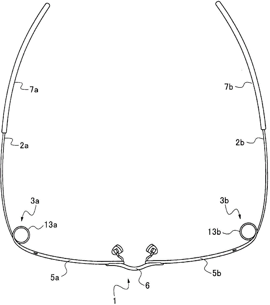
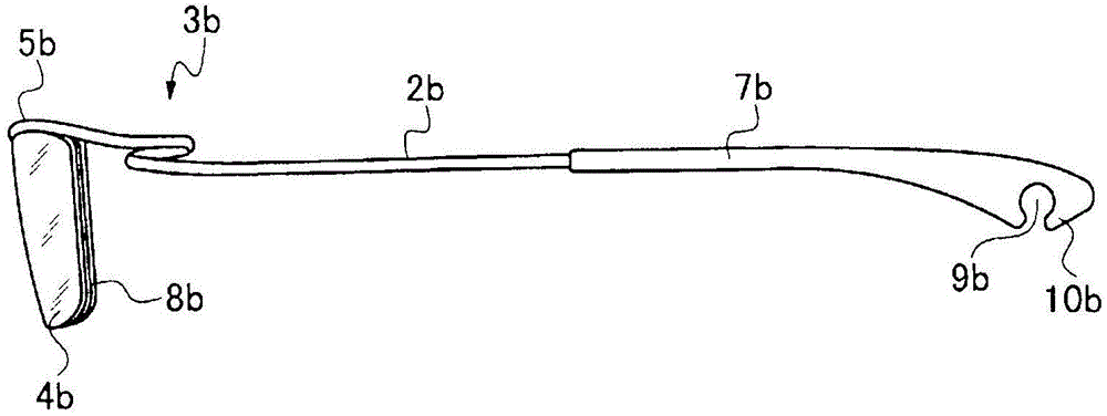
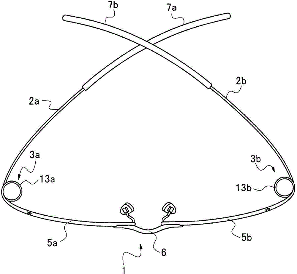
[0033] figure 1 , figure 2 It is a figure showing the spectacle frame of the first embodiment of the present invention, and reference numeral 1 denotes a front part, reference numerals 2a, 2b denote temples, and reference numerals 3a, 3b denote ring joint parts. The lenses 4a, 4b are symmetrically installed on the front part 1. Therefore, the lenses 4a, 4b are held by metal or plastic wires (Japanese: 水系) 8a, 8b, and the two ends of the metal or plastic wires 8a, 8b are fixed to the half frame 5a, 5b.

[0034] The two half-frames 5a, 5b are brazed by the connecting member 6 in the center, and are connected symmetrically. Furthermore, the half-frames 5a, 5b extend outward to form ring joints 3a, 3b, and further extend rearward from the ring joints 3a, 3b to form temples 2a, 2b. That is, the half-frames 5a, 5b, the annular joint portions 3a, 3b, and the temples 2a, 2b are each composed of one continuous wire. Furthermore, resin leg covers (ear hooks) 7a, 7b for hanging on ...


PUM


Abstract

A spectacle frame, wherein a front part (1) for retaining lenses (4a, 4b) and temples (2a, 2b) on both sides of the front part (1) are provided, torsion-coil-spring-shaped ring coupling parts (3a, 3b) are formed by wire rods extending continuously from the front part (1), and the wire rods are further extended from the ring coupling parts (3a, 3b) to form the temples (2a, 2b), whereby the coupling parts are configured without the use of screws, and stable wear is enabled when the spectacle frame is mounted on a face. Engaging pieces (10a, 10b) for engaging with coil parts of the ring coupling parts (3a, 3b) are provided at distal ends of resin end covers (7a, 7b) into which distal-end parts of the temples (2a, 2b) are inserted, and it is thereby possible for the distal-end parts of the temples to be reliably engaged in the vicinity of the coupling parts.

Description

technical field [0001] The present invention relates to a spectacle frame that does not use screws, simplifies assembly, does not cause looseness, and can be worn stably at any time. Background technique [0002] In general, temples are attached to both sides of the front portion of the spectacle frame, and the temples are configured to be foldable through joints such as hinges. Figure 6 It shows a conventional metal spectacle frame. In the front part a, the frames b and b for lens insertion are connected by the connecting member c, and the temples e and e are brazed to the front part a via joints f and f. The pile heads b and b on both sides of the pile are connected. [0003] Although the form of the above-mentioned front part a in the spectacle frame is various, the parts other than the front part are usually installed so that the temples e, e can go to the studs arranged on both sides of the front part a via the joints f, f. b, b folded. In order to store the glasses ...

Claims


Application Information

Patent Timeline
Patent Type & Authority Applications(China)
IPC IPC(8): G02C5/16
CPCG02C5/2272G02C1/04G02C5/143G02C5/16G02C2200/06G02C2200/10G02C2200/22G02C2200/28
Inventor 金谷秀幸
Owner SUZHOU SUNREEVE OPTICAL CO LTD
Learn More