
A High Field Permanent Magnet Magnetic Resonance Imaging Magnet System with Magnetic Focusing and Curved Surface Correction

A technology of magnetic resonance imaging and permanent magnets, applied in permanent magnets, measuring magnetic variables, measuring devices, etc., can solve the problems of small effective shimming space and low efficiency, and achieve high magnetic field stability, high efficiency, and shimming space big effect

Inactive Publication Date: 2016-09-28
谢寰彤
View PDF5 Cites 0 Cited by
  • Summary
  • Abstract
  • Description
  • Claims
  • Application Information

AI Technical Summary

Problems solved by technology

At present, the shimming technology of thin iron sheets is used in the world to correct the magnetic field. Because the iron sheet shimming has edge effects, the effective shimming space is small and the efficiency is low. At present, the highest in foreign countries is between 12-30ppm

Method used


Image

  • A High Field Permanent Magnet Magnetic Resonance Imaging Magnet System with Magnetic Focusing and Curved Surface Correction
  • A High Field Permanent Magnet Magnetic Resonance Imaging Magnet System with Magnetic Focusing and Curved Surface Correction
  • A High Field Permanent Magnet Magnetic Resonance Imaging Magnet System with Magnetic Focusing and Curved Surface Correction

Examples


Embodiment Construction

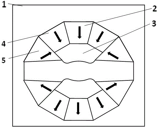
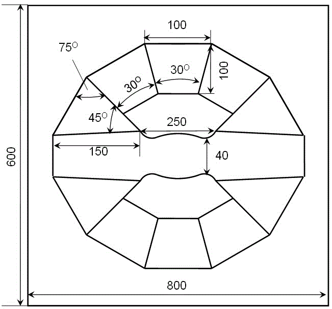
[0019] Two kinds of permanent magnet main magnets were made, one with a main magnetic field strength of 1.5T, a magnetic gap of 40mm, a shimming space of a cylinder with a diameter of 35mm×60mm, a weight of 400kg, and a uniformity of 0.5ppm. The data in Table 2 were used. image 3 The specific dimensions of its components are shown in .

[0020] The other one has a main magnetic field strength of 1.2T, a magnetic gap of 70mm, a shimming space of a cylinder with a diameter of 60mm×100mm, a weight of 1200kg, a space utilization efficiency of 92%, and a magnetic field uniformity of 2ppm. The data in Table 3 is used. Figure 4 The specific dimensions of its components are shown in .

[0021] .


PUM


Abstract

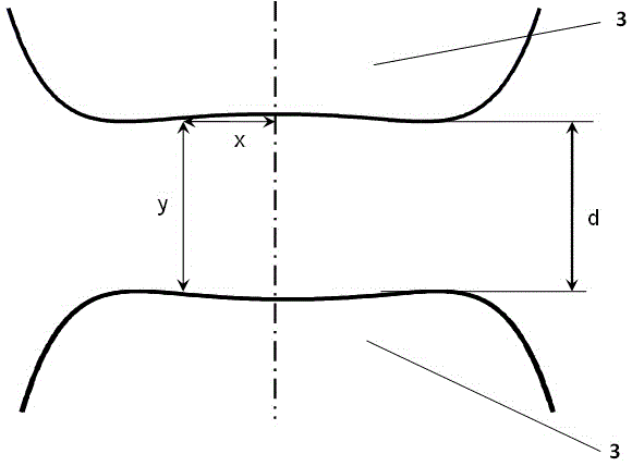
The invention belongs to the technical field of magnetic resonance imaging, and particularly relates to a high-field permanent magnet magnetic resonance imaging magnet system for magnetic focusing and curved surface correction. The magnet system comprises a magnetic yoke, main magnetic steel, non-spherical curved-surface magnetic poles, plugging magnetic steel and side magnetic steel, wherein the non-spherical curved-surface magnetic poles are two saddle-type rotary curved surfaces, have the same shapes and are symmetrically distributed at the center of the magnetic yoke; two pieces of main magnetic steel are respectively positioned behind the two magnetic poles; the plugging magnetic steel is deviated from the center position and is respectively positioned behind the two magnetic poles and positioned on the two side surfaces of the main magnetic steel; the side magnetic steel is respectively positioned on the side surfaces of the two magnetic poles and arranged on the outer side of the plugging magnetic steel; the main magnetic steel and the plugging magnetic steel are made of permanent magnet materials with high coercive force; the side magnetic steel is made of permanent magnet materials with higher coercive force; the coercive force of the side magnetic steel is over 20 percent higher than that of the main magnetic steel. By the adoption of a magnetic focusing technology, high-field 1.2-2.1T field intensity can be achieved; the uniform field of a magnet is corrected by the curved surfaces, so that extremely high space efficiency and more than ten times of uniformity are achieved.

Description

technical field [0001] The invention belongs to the technical field of magnetic resonance imaging, and in particular relates to a novel high-field permanent magnet magnetic resonance imaging magnet system. Background technique [0002] At present, the magnetic resonance imaging system adopts superconducting high field and permanent magnet low field. The advantages of permanent magnet with low maintenance cost and high magnetic field stability have always been valued by researchers. The permanent magnet high field has long been a technical problem that is difficult to overcome. At present, the highest technology of foreign magnetic resonance imaging permanent magnet systems is 1.0T. Magnetic resonance imaging systems require a highly uniform magnetic field, and because magnets have a certain shape, the magnetic field uniformity is low even under the premise of high precision processing. At present, the shimming technology of thin iron sheets is used in the world to correct t...

Claims


Application Information

Patent Timeline
Patent Type & Authority Patents(China)
IPC IPC(8): H01F7/02G01R33/383
Inventor 谢寰彤
Owner 谢寰彤
Learn More