
Foot of humanoid robot and control method thereof

A humanoid robot and robot technology, applied in the field of bionic machinery, can solve the problems of complex control system, poor robot walking gait adjustment ability, and less freedom of foot structure, so as to improve walking speed and stride length and absorb ground impact , enhance the effect of adaptability

Inactive Publication Date: 2015-05-06
HEFEI UNIV OF TECH
View PDF7 Cites 19 Cited by
  • Summary
  • Abstract
  • Description
  • Claims
  • Application Information

AI Technical Summary

Problems solved by technology

The existing problem is: the foot structure proposed at present cannot well imitate the whole process of the foot contacting the ground when the human body walks, and cannot absorb the impact and vibration of the ground well, so it cannot simulate the walking from the heel to the toe The gait characteristics when leaving the ground cannot cope with complex ground conditions, which affects the stability and flexibility of the robot's walking
Since the active joints of most robot feet are not linearly driven and controlled, and the degree of freedom of the foot structure is small, the control system of the foot structure is very complicated, and it does not have the active flexibility and passive stability of the human foot, resulting in the robot walking poor gait adjustment

Method used


Image

  • Foot of humanoid robot and control method thereof
  • Foot of humanoid robot and control method thereof
  • Foot of humanoid robot and control method thereof

Examples


Embodiment Construction

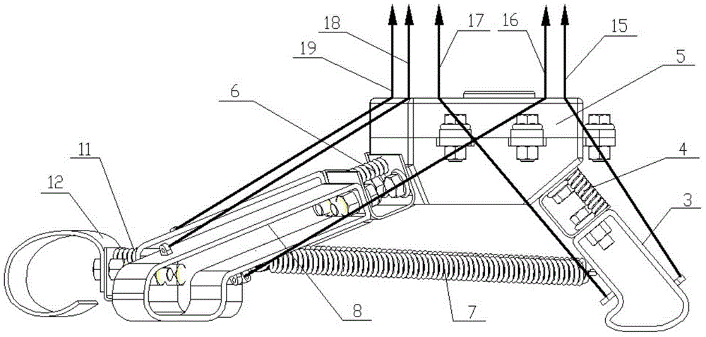
[0029] see figure 1 , the structural form of humanoid robot foot in the present embodiment is:

[0030] An upper plate is set as the talus 5, the rear end surface of the talus 5 is a plane, and the front end surface of the talus 5 is in the shape of a "V" when viewed from above. Three support points are formed for the talus 5 on the rear end surface and the front end surface of the talus 5; the three rods are respectively:

[0031] The calcaneus 3, the upper end of which is supported on the rear end surface of the talus 5 through the heel joint 4;

[0032] Inner metatarsal bone 10, the upper end of which is supported on the medial front face of the talus 5 through the inner metatarsal joint 1;

[0033] Outer metatarsal bone 8, the upper end of which is supported on the outer front face of the talus 5 through the outer metatarsal joint 6;

[0034] Form a rear plantar stress triangle with the lower end of the calcaneus 3 as the rear apex and the pointed head facing backward; ...


PUM


Abstract

The invention discloses the foot of a humanoid robot and a control method of the foot of the humanoid robot. The foot of the humanoid robot is characterized in that an upper disc body is arranged to serve as an ankle bone, the rear end face of the ankle bone is a plane, the front end face of the ankle bone is in a V shape when the front end face of the ankle bone is overlooked, an outer front end face body and an inner front end face body are symmetrically arranged on the V-shaped front end face, the ankle bone is supported in a three-force-point mode through three rod pieces on the rear end face and the front end face of the ankle bone, the three rod pieces refer to a heel bone, an inner metatarsal bone and an outer metatarsal bone, a rear planta pedis stress triangle is formed with the lower end of the ankle bone as a rear vertex and a point head facing backwards, and the upper end face of the ankle bone is connected with the lower limbs of the robot through ankle joints. According to the foot of the humanoid robot and the control method of the foot of the humanoid robot, linear driving devices are arranged on the lower limbs of the robot, all components are driven through flexible ropes according to set actions, and thus rotation of the foot joints of the robot is driven and controlled.

Description

technical field [0001] The invention discloses a humanoid robot foot with the walking ground-touching behavior mode and performance of the bionic human foot, which belongs to the field of bionic machinery. Background technique [0002] Humanoid robots are robots designed and manufactured to imitate human shapes and behaviors. Humanoid robots have strong environmental adaptability and wide application potential, but stiff walking gait and poor walking stability have always been the bottlenecks that curb their wide application. . Therefore, the design research of the bionic robot foot is one of the breakthrough points to improve and enhance the walking stability of the robot. Designing a bionic foot with the functional characteristics of human feet is one of the breakthrough points to improve the walking stability of humanoid robots and enhance the environmental adaptability of humanoid robots, and it is an important point to promote humanoid robots to the application field. ...

Claims


Application Information

Patent Timeline
IPC IPC(8): B62D57/032B62D57/02
CPCB62D57/02B62D57/032Y10S901/01
Inventor 胡小春胡龙翔陈洋周福静董玉德
Owner HEFEI UNIV OF TECH
Learn More