Printing head and image forming device

A printing head and printing element technology, applied in printing and other directions, can solve the problems of reduced printing quality, inability to stabilize the laminate structure, and component positioning, and achieve the effect that the printing quality will not be reduced

Active Publication Date: 2015-05-06
OKI ELECTRIC IND CO LTD
View PDF4 Cites 0 Cited by
  • Summary
  • Abstract
  • Description
  • Claims
  • Application Information

AI Technical Summary

Problems solved by technology

[0008] However, in the above-mentioned conventional print head, if the size of the buffer plate varies, the force of the spring frame to press the buffer plate will vary, so that the structure of

Method used


Image

  • Printing head and image forming device
  • Printing head and image forming device
  • Printing head and image forming device

Examples


Embodiment Construction

[0032] Hereinafter, embodiments of the present invention will be described in detail with reference to the drawings. In this case, a dot-line printer as an image forming apparatus will be described.

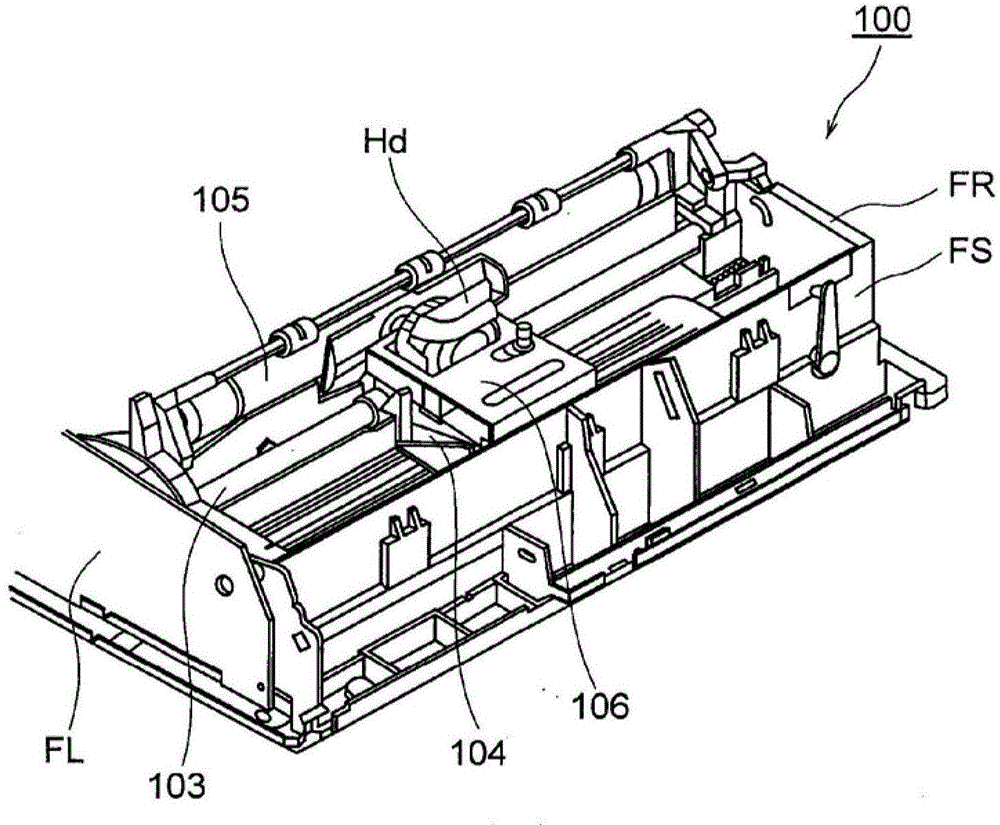
[0033] figure 2 It is a perspective view of the printer according to the embodiment of the present invention.

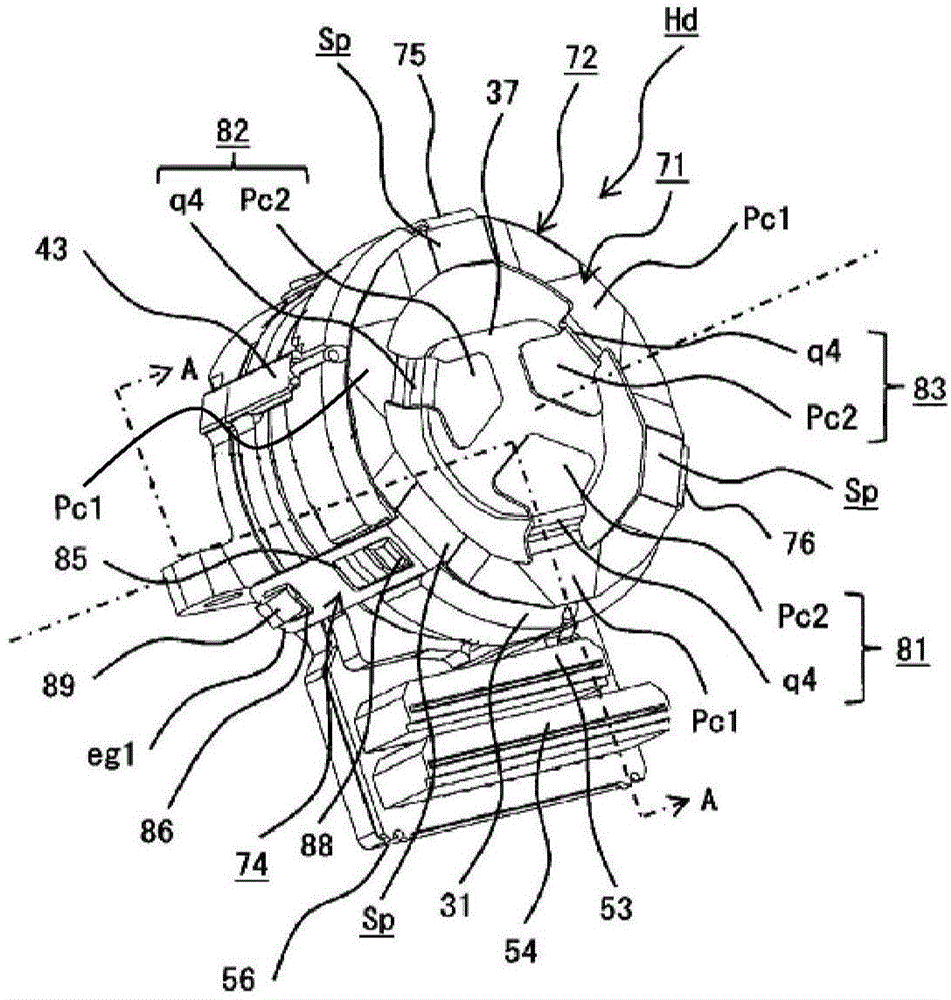
[0034] In the figure, reference numeral 100 denotes a printer (printing device), reference numerals FL and FR denote side frames serving as first and second frames disposed on the left and right sides of the printer 100, and reference numeral FS denotes side frames FL, FR, and A space frame serving as a third frame extending between the FRs, reference numeral 103 denotes a guide shaft extending between the side frames FL and FR and having a circular cross section, and reference numeral 104 denotes a space frame along the guide shaft 103. The carrier that moves (reciprocates) in the left-right direction of the printer 100, reference numeral Hd represents a swing type ...


PUM


Abstract

The invention provides a printing head and an image forming device which enables a construction of a laminated body to be stable and which can reliably perform holding and clamping so as to position various parts of the laminated body on prescribed positions. The printing head has a printing head main body which forms by means laminating various parts which are a guiding head portion (55) which guides a printing element, a printing element driving portion unit which drives the printing element, a cover (31) and an anti-vibration part (37); and a clamping part which is assembled on the printing head main body and fixes the various parts in a laminated direction. The clamping part has a clipping part clipping the guiding head portion (55) and an arm portion used for abutted joint with the anti-vibration part (37). Two pressing forces are generated when the clamping part is assembled on the printing head main body. The clamping part can be independently pressed on the cover (31) and the anti-vibration part (37). Thus the pressing force pressing the cover (31) by the clamping part will not deviate.

Description

technical field [0001] The present invention relates to a print head and an image forming apparatus. Background technique [0002] Currently, in image forming apparatuses such as printers, copiers, facsimile machines, and multifunction machines, such as wire dot printers, a print head is provided, and a plurality of print lines provided on the print head are selectively It advances and hits the ink ribbon, and transfers the ink of the ink ribbon to the paper arranged on the platen, thereby forming dots on the paper and printing. [0003] Therefore, the print head is provided with an armature in a swingable manner, the printing wire is attached to the end of the armature, and in order to rotate the armature, an iron core is provided, wound on the The coil of the iron core, the spring holding the armature, and the like. [0004] In addition, in a clapper print head, a driving current is supplied to a coil to generate a magnetic flux, whereby the armature is attracted by the ...

Claims


Application Information

Patent Timeline
IPC IPC(8): B41J2/23
Inventor 中道健太
Owner OKI ELECTRIC IND CO LTD
Why Eureka
Try Eureka