Motor acceleration apparatus and method

An acceleration device and voltage technology, applied in motor control, AC motor control, motor generator/starter, etc.

Inactive Publication Date: 2015-04-29
SAMSUNG ELECTRO MECHANICS CO LTD
View PDF9 Cites 2 Cited by
  • Summary
  • Abstract
  • Description
  • Claims
  • Application Information

AI Technical Summary

Problems solved by technology

[0015] But in this control of SRM, a large torque is required to make the peak current become larger at the initial start or acceleration

Method used


Image

  • Motor acceleration apparatus and method
  • Motor acceleration apparatus and method
  • Motor acceleration apparatus and method

Examples


Embodiment Construction

[0046] The above and other objects, features and advantages of the present invention will be more clearly understood from the following detailed description of preferred embodiments in conjunction with the accompanying drawings. Throughout the drawings, the same reference numerals are used to designate the same or similar components and redundant descriptions thereof are omitted. Also, in the following description, the terms “first”, “second”, “one side”, “the other side” etc. are used to distinguish a specific component from another component, but the structures of these elements should not be construed as understood to be limited by terminology. Further, in the description of the present invention, when it is determined that a detailed description of related art will obscure the gist of the present invention, its description will be omitted.

[0047] Hereinafter, preferred embodiments of the present invention will be described in detail with reference to the accompanying dr...


PUM


Abstract

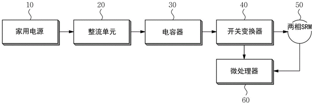
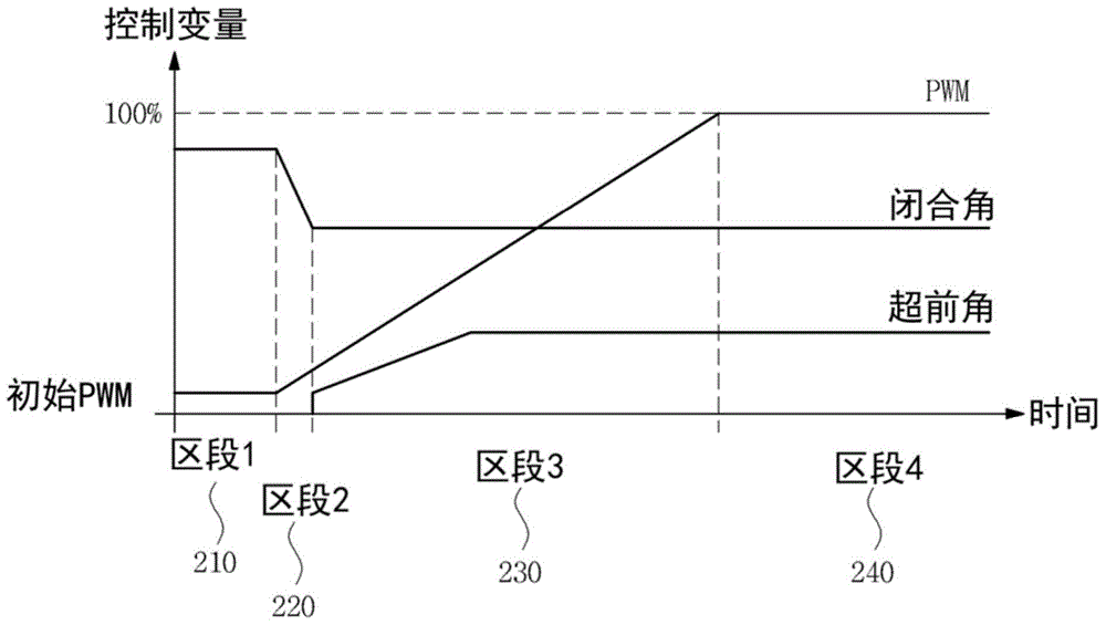
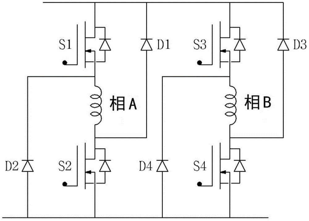
Disclosed herein are a motor acceleration apparatus and a motor acceleration method. The motor acceleration apparatus includes: a rectifying unit converting household power into direct current (DC) voltage to output the converted DC voltage; a switching converter switching the DC voltage output from the rectifying unit in an alternating current manner so as to drive a two-phase switched reluctance motor (SRM) ; and a microprocessor controlling the switching converter at the time of initial acceleration of the two-phase SRM so that an initially set dwell angle is changed to a dwell angle in a normal operation state and starting advanced-angle control.

Description

[0001] Cross-references to related fields [0002] This application claims the benefit of Korean Patent Application No. 10-2013-0123528, filed Oct. 16, 2013, entitled "Motor Acceleration Apparatus and Method," the entire contents of which are incorporated herein by reference. technical field [0003] The invention relates to a motor acceleration device and a motor acceleration method. Background technique [0004] Switched reluctance motors (SRMs) are one of the older motors that have been in use for over 150 years. Since power semiconductors have been developed, this traditional type of reluctance motor has become known as switched reluctance motor to meet the needs of variable drives. [0005] 'Switched Reluctance' is named by S.A. Nasar, which means two main features of SRM. [0006] Firstly, the expression "switching" means that the motor should always be operated in a continuous switching pattern. According to the research and development and progress of new power se...

Claims


Application Information

Patent Timeline
Patent Type & Authority Applications(China)
IPC IPC(8): H02P23/00H02P27/08
CPCH02P1/163H02P31/00H02P25/0925H02P25/092H02P25/08
Inventor 孙廷虎禹武善申洪澈金大成
Owner SAMSUNG ELECTRO MECHANICS CO LTD
Why Eureka
Try Eureka