Small-resistance-value grounding grid of large device and design construction method

A large-scale equipment and grounding grid technology, applied in the direction of connection, connection contact material, electrical components, etc., can solve the problems of increasing construction difficulty, low soil resistivity, easy to collapse, etc., to avoid the increase of dosage and increase Conductive interface, the effect of reducing construction costs

Active Publication Date: 2015-04-29
中铁二十一局集团第二工程有限公司
View PDF10 Cites 11 Cited by
  • Summary
  • Abstract
  • Description
  • Claims
  • Application Information

AI Technical Summary

Problems solved by technology

The location of the magnetic grounding network is close to the Yellow River. On the one hand, the soil resistivity is low, but on the other hand, it increases the difficulty of construction. During the construction of the vertical grounding pole, the resistance reducing agent is easy to be lost with the movement of the quicksand layer, especially in the vertical grounding pole. Subsidence is prone to occur during construction, and it is found from the foundation survey report that within a certain depth there are construction waste and sand interbedded with stone backfill layers, making the soil resistivity reach 67Ω. About m, what is more difficult is that the construction unit proposed to use only 2000 square meters of green area as the land for the grounding grid. Through calculation, the product of the land area and the resistance of the grounding grid is 370, and generally this value has reached more than 700 , so there is no experience in China to learn from. Using such a small-area grounding grid to ensure the safety of equipment is a major technical problem we face

Method used


Image

  • Small-resistance-value grounding grid of large device and design construction method
  • Small-resistance-value grounding grid of large device and design construction method
  • Small-resistance-value grounding grid of large device and design construction method

Examples


Embodiment 1

[0036] Method embodiment 1, a method for designing and constructing a small-resistance grounding grid for large-scale equipment in a water-rich and high-water level area; including the following steps:

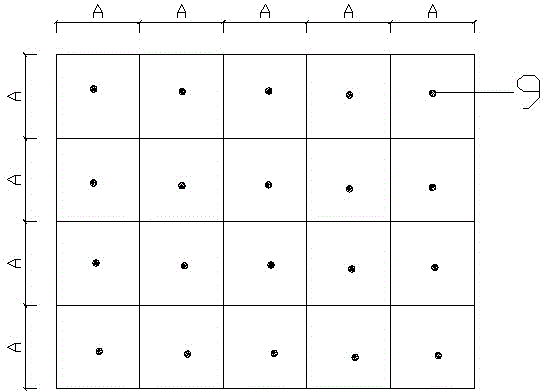
[0037] a. Determination of soil resistivity: figure 1 As shown, in the case of no rainfall and relatively dry weather within one week before the test, the grounding grid area is divided into grids with a side length A of 10×10 meters, and the soil is determined according to the four-line method after manual excavation to a depth of 1 meter. Resistivity test point 9, after using the ZC-8 grounding resistance tester to test the resistivity, take the maximum value as the design soil resistivity.

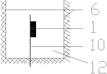
[0038] b. Determination of the burial depth of the horizontal grounding electrode and the vertical grounding electrode: the maximum thickness of frozen soil in winter, plus the optimal conductive distance of the soil, determines that the burial depth of the horizontal grounding electrod...


PUM


Abstract

The invention provides a small-resistance-value grounding grid of a large device. The small-resistance-value grounding grid comprises horizontal grounding electrodes and vertical grounding electrodes. The horizontal grounding electrodes are arranged under the ground and are arranged vertically and horizontally to form a horizontal grounding electrode planar grid. A plurality of vertical grounding electrodes are perpendicular to the horizontal grounding electrode planar grid, are arranged at multiple joints of the horizontal grounding electrodes arranged vertically and horizontally and are connected with the horizontal grounding electrodes through arc-shaped clamps. A grounding grid extraction electrode is roughly arranged at the center of the horizontal grounding planar grid. The lower portions of the vertical grounding electrodes are arranged on thin-wall iron sheet protection cylinders, resistance reducing agents are poured into the thin-wall iron sheet protection cylinders, and the cylinder walls of the thin-wall iron sheet protection cylinders are provided with holes. The horizontal grounding electrodes are arranged in trenches, and the bottom faces of the trenches are provided with supporting rods. The horizontal grounding electrodes are fixed to the supporting rods and located in the centers of the cross sections of the trenches, and the resistance reducing agents are poured into the trenches. By means of the small-resistance-value grounding grid, the construction cost is lowered, land is saved, the small-resistance-value grounding grid is finished in a small area, the stability of the grounding effect is guaranteed, and safe and stable operation of a grounding device is guaranteed.

Description

technical field [0001] The invention belongs to the technical field of house construction electrical engineering and large-scale equipment grounding, and in particular relates to a small-resistance grounding grid for large-scale equipment, and also relates to a design and construction method for the small-resistance grounding grid for large-scale equipment. Background technique [0002] The first phase project of Lanzhou Heavy Ion Medical Research Center and Testing and Commissioning Center of Institute of Modern Physics, Chinese Academy of Sciences is an industrial plant integrating R&D, production, commissioning and maintenance. The cost of a single magnet power supply is about 5 million. During commissioning, in order to avoid overvoltage , Overcurrent damages the equipment and suppresses the impact of overcurrent on equipment debugging. Based on calculations, the Institute of Near Physics, Chinese Academy of Sciences puts forward the requirement for a 0.2Ω resistance grou...

Claims


Application Information

Patent Timeline
IPC IPC(8): H01R4/66H01R43/00
CPCH01R4/66H01R43/00
Inventor 魏磊李学军张发祥徐亚伟郭瑞朱冠生蒙悟李国庆李葆萍刘琦刘策
Owner 中铁二十一局集团第二工程有限公司
Why Eureka
Try Eureka