
Optical sight orientation positioning fastener

A directional positioning and sighting technology, applied in weapon accessories, offensive equipment, etc., can solve the problems of small activity space, ineffective compatibility, aiming deviation, etc., to achieve the effect of stable connection, avoiding shooting deviation and high positioning accuracy

Inactive Publication Date: 2015-04-29
邢建功
View PDF4 Cites 2 Cited by
  • Summary
  • Abstract
  • Description
  • Claims
  • Application Information

AI Technical Summary

Problems solved by technology

[0002] At present, the scope connection mechanism of the 95 gun family is connected through a dovetail groove and a dovetail guide rail. There are many defects in this connection method: 1. Before live ammunition shooting, the scope needs to be adjusted, and the scope needs to be maintained and disassembled after calibration. When the scope is reinstalled for the second time, there will be aiming deviation, which will seriously affect the shooting accuracy, and a second calibration is required; 2. There are more and more types of sighting equipment, but the locking mechanism of the sighting equipment is difficult to construct and install. The parts and fastening methods are not effectively compatible, and the versatility is poor; the movable space between the battery compartment at the lower part of the scope of the 3.95 gun family and the gauge seat of the firearm is too small, which makes it impossible to replace the battery after the scope is installed.

Method used


Image

  • Optical sight orientation positioning fastener
  • Optical sight orientation positioning fastener
  • Optical sight orientation positioning fastener

Examples


Embodiment Construction

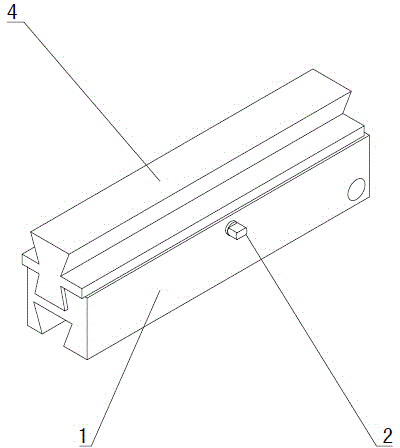
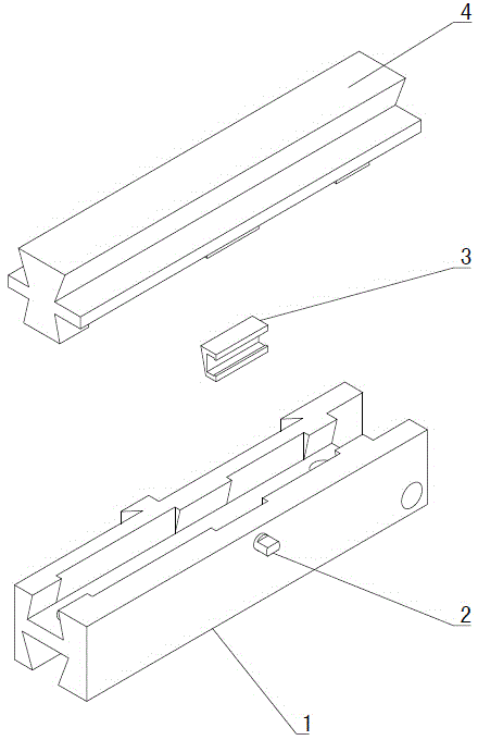
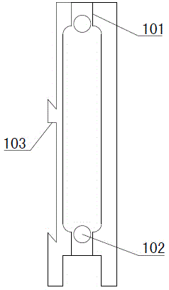
[0030] Figure 1~9 It is the best embodiment of the present invention, below in conjunction with attached Figure 1~9 The present invention will be further described.

[0031] A scope directional positioning fastener, comprising a fixed base 1 and a scope fixed base 4, the lower part of the fixed base 1 is provided with an installation part for fixed connection with firearms, the upper part of the fixed base 1 is provided with a longitudinal chute 104, and the scope is fixed The lower part of the seat 4 is installed in the chute 104, and the fixed base 1 is provided with a horizontal fastening mechanism for horizontally fastening the scope fixed seat 4, and the same side of the scope fixed seat 4 and the fixed base 1 are provided with a mutual clamp The directional positioning mechanism, the scope fixed seat 4 top is provided with the scope fixing part 403 of fixing scope. The scope directional positioning fastener of the present invention installs the scope on the firearm t...


PUM


Abstract

The invention belongs to the technical field of light weapon aiming auxiliary devices and particularly relates to an optical sight orientation positioning fastener. The optical sight orientation positioning fastener is characterized by comprising a fixing base (1) and an optical sight fixing seat (4), wherein an installing portion fixedly connected with a firearm is arranged at the lower portion of the fixing base (1), a longitudinal chute (104) is formed in the upper portion of the fixing base (1), the lower portion of the optical sight fixing seat (4) is installed in the longitudinal chute (104), a transverse fastening mechanism for transversely fastening the optical sight fixing seat (4) is arranged on the fixing base (1), orientation positioning mechanisms fastened mutually are arranged on the side face on the same side of the optical sight fixing seat (4) and the fixing base (1), and an optical sight fixing portion (403) for fixing an optical sight is arranged at the upper portion of the optical sight fixing seat (4). The optical sight orientation positioning fastener is simple in structure and can be installed and played, and a battery is convenient to replace after the optical sight is installed and fixed.

Description

technical field [0001] A scope directional positioning fastener belongs to the technical field of aiming auxiliary devices for light weapons, and in particular relates to a scope directional positioning fastener. Background technique [0002] At present, the scope connection mechanism of the 95 gun family is connected by a dovetail groove and a dovetail guide rail. There are many defects in this connection method: 1. Before live ammunition shooting, the scope needs to be adjusted, and the scope needs to be maintained and disassembled after calibration. When the scope is reinstalled for the second time, there will be aiming deviation, which will seriously affect the shooting accuracy, and a second calibration is required; 2. There are more and more types of sighting equipment, but the locking mechanism of the sighting equipment is difficult to construct and install. The parts and fastening methods are not effectively compatible, and the versatility is poor; the movable space ...

Claims


Application Information

Patent Timeline
IPC IPC(8): F41G11/00F41C27/00
Inventor 邢建功韩培勇
Owner 邢建功
Learn More