Usage strategy for mixed gasoline and CNG fueled vehicles

A fuel and fuel tank technology, applied in the direction of fuel injection control, combustion engine, internal combustion piston engine, etc., can solve the problem of insufficient control of fuel usage

Inactive Publication Date: 2015-04-29
FORD GLOBAL TECH LLC
View PDF6 Cites 2 Cited by
  • Summary
  • Abstract
  • Description
  • Claims
  • Application Information

AI Technical Summary

Problems solved by technology

Although fuel usage strategies have been developed for vehicles with multiple fuel tanks, these schemes are insufficient to control fuel usage in vehicles with a single blended fuel tank

Method used


Image

  • Usage strategy for mixed gasoline and CNG fueled vehicles
  • Usage strategy for mixed gasoline and CNG fueled vehicles
  • Usage strategy for mixed gasoline and CNG fueled vehicles

Examples


Embodiment Construction

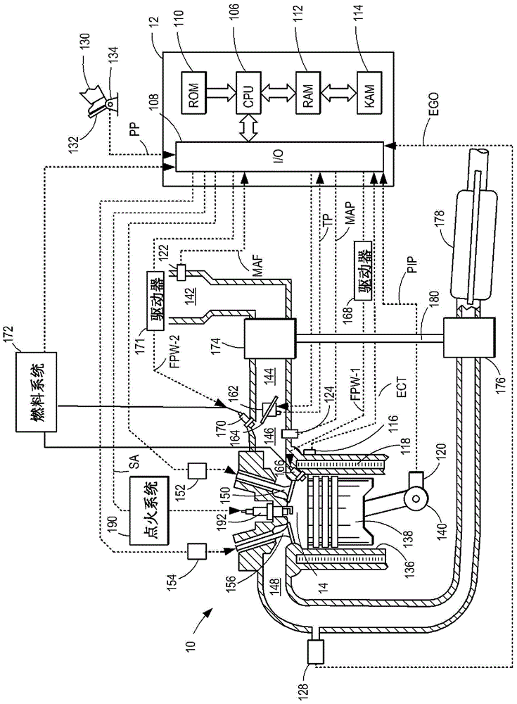
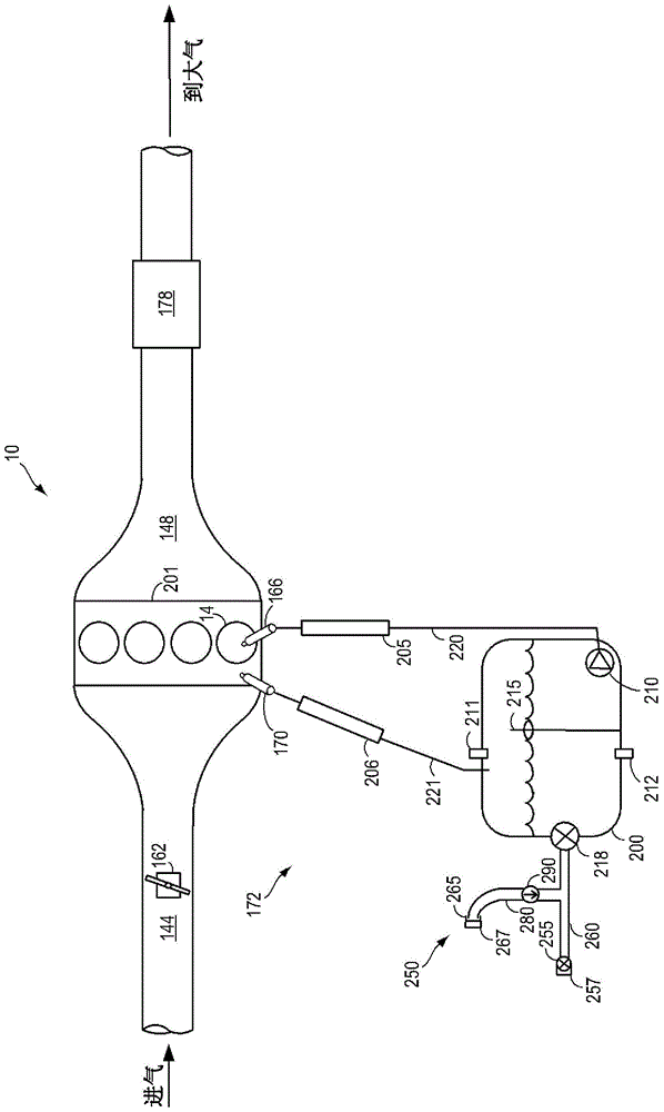
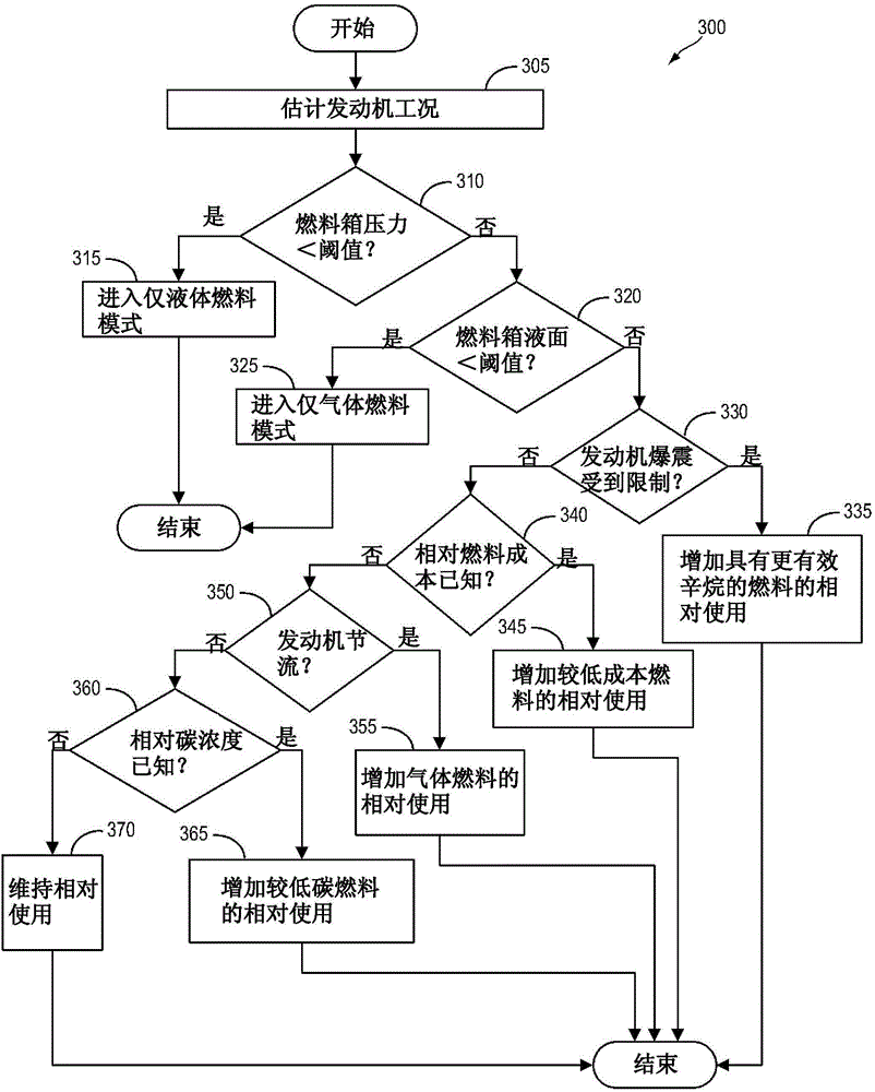
[0013] The present invention relates to systems and methods for fuel usage strategies for engine systems including fuel systems operating on both liquid and gaseous fuels, where the two fuels are stored together in a high pressure fuel tank. The engine system may include configurations such as figure 1 Port fuel injector and direct fuel injector cylinders are shown. The engine system may include a multi-cylinder engine coupled to a fuel system having a fuel delivery system as described in 2. image 3 The diagram illustrates the use of figure 1 with figure 2 An example approach to a fuel usage strategy for an engine system as described in .

[0014] figure 1 An example embodiment of a combustion chamber or cylinder of internal combustion engine 10 is described. Engine 10 may be controlled at least partially by a control system including controller 12 and by input from a vehicle operator 130 via an input device 132 . In this example, input device 132 includes an accelerat...


PUM


Abstract

A method for an engine, comprising: responsive to a pressure in a fuel tank being below a pressure threshold, injecting only a liquid fuel into an engine cylinder, the fuel tank storing the liquid fuel and a pressurized gaseous fuel partially dissolved in the liquid fuel. In this way, the pressurized gaseous fuel may be conserved, thus maintaining a pressure gradient within the fuel system and allowing for judicious use of the pressurized gaseous fuel, for example during cold start conditions.

Description

technical field [0001] This application relates to usage strategies for gasoline-CNG blend fueled vehicles. Background technique [0002] Compressed natural gas (CNG) is a high octane fuel that is beneficial for reducing engine knock, for reducing hydrocarbon emissions during cold start events, and for reducing carbon dioxide emissions during engine operation. However, CNG has a lower energy density compared to liquid fuels such as diesel fuel or gasoline. This typically requires encapsulation of CNG in cryogenic cylinders (in the form of liquefied natural gas (LNG)) or in high pressure tanks (approximately 200-250 atmospheres). [0003] To increase distance and the total amount of fuel stored in the vehicle, CNG can be used in conjunction with gasoline or diesel fuel, requiring the vehicle to switch between fuels for optimum performance. However, for all vehicles, space constraints do not allow the inclusion of a separate fuel tank. A preferred system may be one that sto...

Claims


Application Information

Patent Timeline
Patent Type & Authority Applications(China)
IPC IPC(8): F02D41/30F02D19/06
CPCF02P5/045F02P5/1527F02D19/0615F02D19/0628F02D19/081F02D35/027F02D37/02F02D41/0025F02D2200/0404F02D2200/0406F02D2200/0611Y02T10/30F02D41/0027F02D41/3094
Inventor T·G·里昂M·A·德尔斯J·N·阿勒瑞D·K·拜德尼G·苏尔尼拉
Owner FORD GLOBAL TECH LLC
Why Eureka
Try Eureka