
Dispensing laser mechanism

A laser and glue dispensing technology, which is applied in the direction of coating, liquid coating device on the surface, etc., can solve the problems of inaccurate positioning, easy loosening of small parts, and time-consuming problems, so as to achieve accurate dispensing position and improve The effect of improving product quality and improving production efficiency

Inactive Publication Date: 2015-04-29
BOZHON PRECISION IND TECH CO LTD
View PDF4 Cites 0 Cited by
  • Summary
  • Abstract
  • Description
  • Claims
  • Application Information

AI Technical Summary

Problems solved by technology

The existing technology is generally manual dispensing. Due to the small size of small parts, it is not easy to achieve positioning, resulting in more time-consuming manual assembly, and it is easy to cause fatigue of workers, and small parts after assembly are prone to loosening and inaccurate positioning. and other quality problems; and the amount of glue dispensed cannot be controlled during the dispensing process, and the amount of glue in the glue cartridge cannot be detected, resulting in inaccurate dispensing process

Method used


Image

  • Dispensing laser mechanism
  • Dispensing laser mechanism
  • Dispensing laser mechanism

Examples


Embodiment Construction

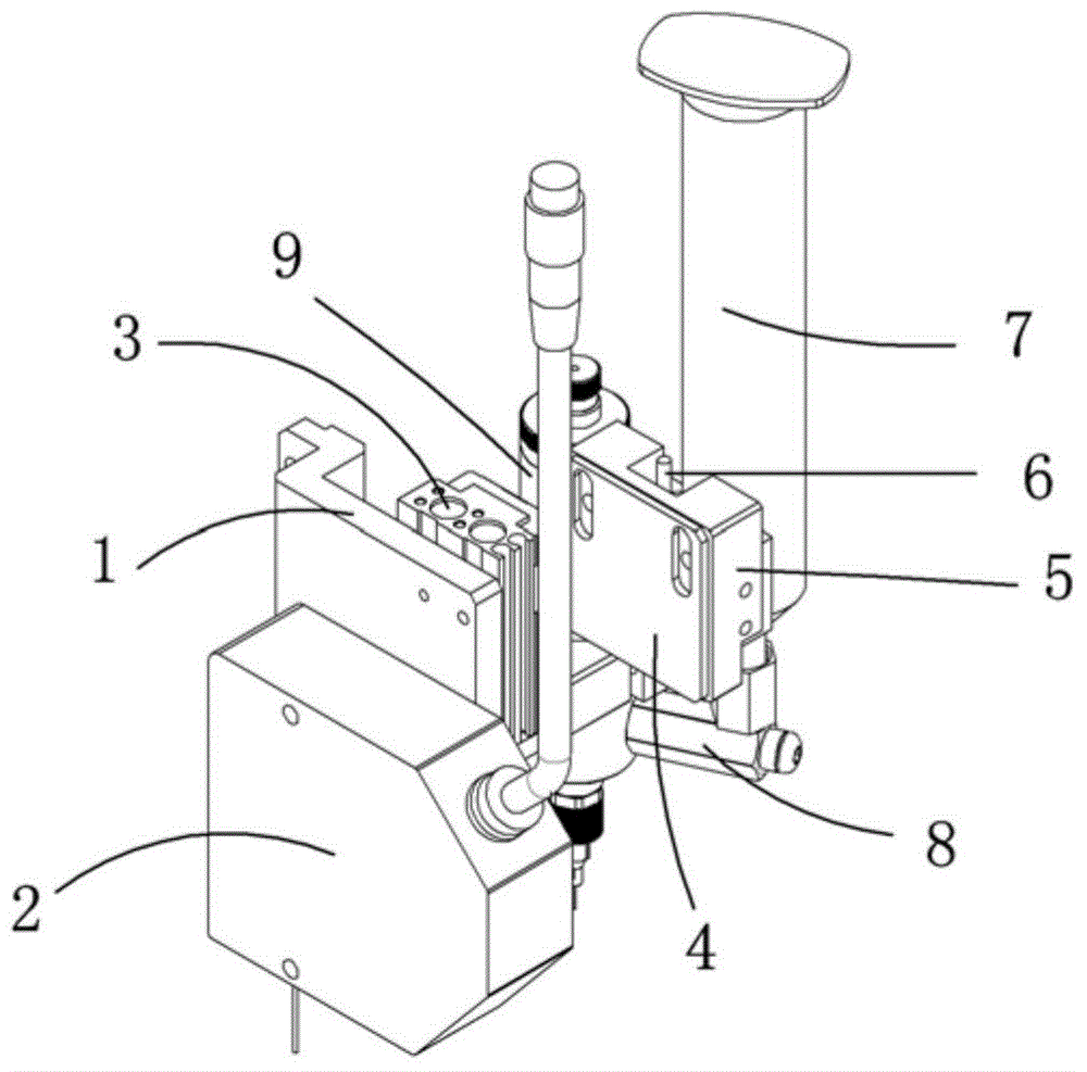
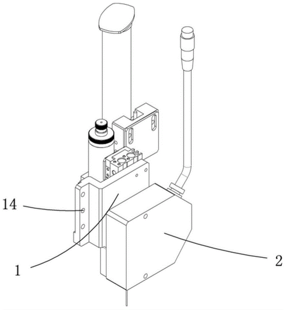
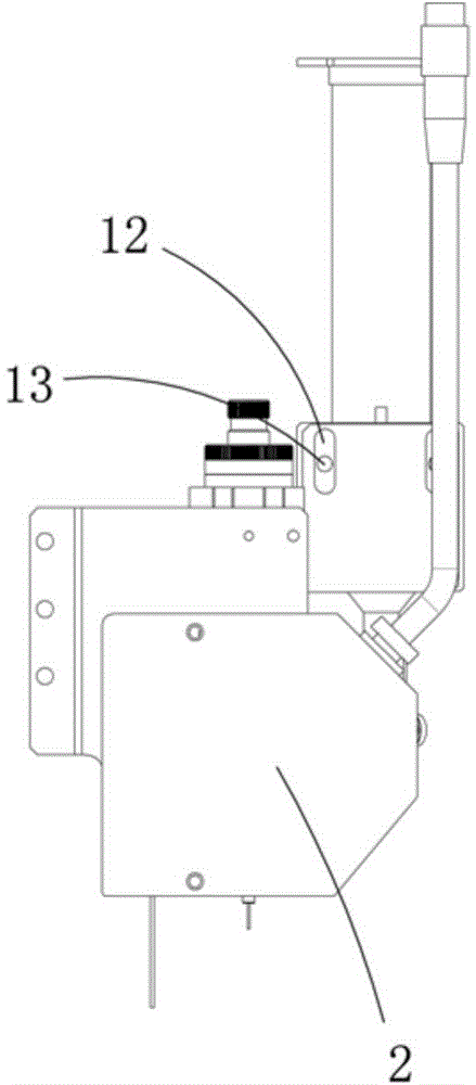
[0018] Examples, see attached Figure 1~6 , a dispensing laser mechanism, which includes a laser fixing plate 1, a laser 2, a dispensing valve lifting cylinder 3, a sensor mounting plate 4, a sensor fixing block 5, a sensor 6, a rubber cylinder 7, a glue connecting elbow 8, a dispensing Valve 9, dispensing valve clamping block a10 and dispensing valve clamping block b11, the outer side of the laser fixing plate is fixedly installed with the laser, and the inner side of the laser fixing plate is fixedly installing the dispensing valve lifting cylinder; the dispensing valve The lifting cylinder is connected with a lifting plate, the dispensing valve clamping block a is fixed on the lifting plate, and the dispensing valve is installed on the lifting plate through the dispensing valve clamping block a and the dispensing valve clamping block b; The sensor mounting plate is installed on the upper side of the lifting plate, the sensor fixing block is installed on the sensor mounting ...


PUM


Abstract

The invention relates to a dispensing laser mechanism. The dispensing laser mechanism is characterized in that a laser part is fixedly arranged at the outer side of the laser fixing plate, and a dispensing-valve lifting cylinder is fixedly arranged at the inner side of the laser fixing plate; a lifting plate is connected on the dispensing-valve lifting cylinder, a dispensing-valve clamping block a is fixed on the lifting plate, a dispensing valve is arranged on the lifting plate by the dispensing-valve clamping block a and a dispensing-valve clamping block b; a sensor installing plate is arranged at the upper side of the lifting plate, and a sensor fixing block is arranged on the sensor installing plate and is provided with a sensor; and one side of a glue drum is close to the sensor, and the lower end of the glue drum is communicated together with the dispensing valve by a glue-connecting elbow. The dispensing laser mechanism has the advantages that when the dispensing laser mechanism moves to the dispensing position, the laser part measures the dispensing height and calculates the glue discharging amount; the sensor is used for detecting the glue amount in the glue drum; and the dispensing valve moves to the dispensing position to carry out dispensing, and can be used for accurately measuring the dispensing height and measuring the glue amount, and the laser part is convenient for controlling the glue discharging amount.

Description

Technical field: [0001] The invention relates to a glue dispensing laser mechanism. Background technique: [0002] In the production process of electronic products, it is necessary to assemble some small parts to electronic products, and sometimes it is necessary to use dispensing valves to dispense glue. The existing technology is generally manual dispensing. Due to the small size of small parts, it is not easy to achieve positioning, resulting in more time-consuming manual assembly, and it is easy to cause fatigue of workers. Moreover, small parts after assembly are prone to loosening and inaccurate positioning. and other quality problems; moreover, the amount of glue dispensing cannot be controlled during the dispensing process, and the amount of glue in the glue cartridge cannot be detected, resulting in inaccurate dispensing process. Therefore it is necessary to design a kind of dispensing laser mechanism. Invention content: [0003] The purpose of the present inven...

Claims


Application Information

Patent Timeline
Patent Type & Authority Applications(China)
IPC IPC(8): B05C5/00B05C11/10
CPCB05C5/00B05C11/101B05C11/1018
Inventor 吕绍林汪炉生朱晓锋叶友乐聂星李星
Owner BOZHON PRECISION IND TECH CO LTD
Learn More