UPS multiple output intelligent control system and UPS multiple output intelligent control method
An intelligent control system and multi-output technology, applied in the field of UPS, can solve problems such as power supply failure, insufficient intelligence, and inability to ensure continuous power supply of important loads, and achieve the effect of cost reduction and intelligent control methods
- Summary
- Abstract
- Description
- Claims
- Application Information
AI Technical Summary
Problems solved by technology
Method used
Image
Examples
Embodiment 1
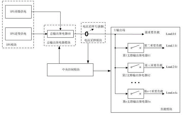
[0041] Such as figure 1 As shown, this embodiment provides a UPS multi-output intelligent control system, including: a UPS multi-output intelligent control system, including: a UPS module, including a UPS inverter power supply unit and a UPS bypass power supply unit for Supply power to various loads;
[0042] A central control module and a total output relay module, a load module and a current sampling module connected to the central control module;
[0043] The total output relay module includes a total output relay S0, and the total output relay module is connected to the load module through the current sampling module to realize the connection and disconnection of the load module;
[0044] The load module includes a main output circuit and n branches, the main output circuit is provided with a load Load0, and the n branches are respectively provided with output relays S1, S2, S3...Sn, and the The output relays S1-Sn are respectively connected in series wit...
Embodiment 2
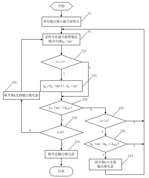
[0051] Such as figure 2 As shown, the present embodiment provides a control method for a UPS multi-output intelligent control system, comprising the following steps:
[0052] Step S1: The UPS module starts to supply power, the total output relay S0 in the total output relay module and the n branch output relays S1-Sn in the load module are all connected to connect all loads Load0-Loadn to the UPS module, where n is an integer greater than or equal to 0;
[0053] Step S2: The current sampling transformer L in the current sampling module samples the total output current of the current cycle , and stored in the central control module; where , Indicates the main output circuit current, The kth branch current in the table, k=0, 1, 2,..., n, m means that there are m loads connected to the UPS in the current cycle, m=k+1;
[0054] Step S3: The central control module judges the total output current of the current cycle Is it greater than the given total output current , ...
PUM
 Abstract
Description
Claims
Application Information
 - R&D
- Intellectual Property
- Life Sciences
- Materials
- Tech Scout
- Unparalleled Data Quality
- Higher Quality Content
- 60% Fewer Hallucinations
Browse by: Latest US Patents, China's latest patents, Technical Efficacy Thesaurus, Application Domain, Technology Topic, Popular Technical Reports.
© 2025 PatSnap. All rights reserved.Legal|Privacy policy|Modern Slavery Act Transparency Statement|Sitemap|About US| Contact US: help@patsnap.com


