Eureka AIR delivers breakthrough ideas for toughest innovation challenges, trusted by R&D personnel around the world.

Movable type location method based on magnetic gradient tensor and geomagnetic vector measurement

A magnetic gradient tensor and positioning method technology, applied in the field of magnetic measurement, can solve the problems of inability to dynamically determine the three-dimensional coordinate system of the magnetic target in real time and the lack of research on moving three-dimensional positioning.

Active Publication Date: 2015-04-22
NAT UNIV OF DEFENSE TECH
View PDF4 Cites 34 Cited by
  • Summary
  • Abstract
  • Description
  • Claims
  • Application Information

AI Technical Summary

Problems solved by technology

However, the total sensor can only judge the presence or absence, or it needs repeated detection to determine the approximate position of the target, and cannot dynamically determine the three-dimensional coordinate system of the magnetic target in real time.
[0005] To sum up, in terms of magnetic target positioning, it is mainly static positioning, that is, positioning is performed when the array is not moving; or the total sensor is used for moving magnetic target signal detection, but there is a lack of research on moving three-dimensional positioning

Method used


Image

  • Movable type location method based on magnetic gradient tensor and geomagnetic vector measurement
  • Movable type location method based on magnetic gradient tensor and geomagnetic vector measurement
  • Movable type location method based on magnetic gradient tensor and geomagnetic vector measurement

Examples


Embodiment Construction

[0041] Below, the present invention will be further described in conjunction with the accompanying drawings and specific embodiments. In order to better understand the technical solution of the present invention, its principles and calculation formulas will now be deduced in detail in conjunction with specific embodiments and described in detail as follows:

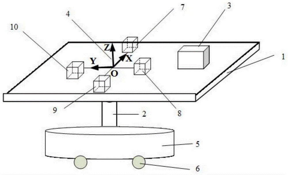
[0042] Such as figure 2 As shown, the non-magnetic moving device includes a non-magnetic platform 1, a platform support shaft 2, a non-magnetic base 5 and a moving pulley 6, the platform support shaft 2 is installed on the non-magnetic base 5, and the platform support shaft 2 is connected to the non-magnetic The magnetic platform 1 is connected to and supports the non-magnetic platform 1, and the moving pulley 6 is installed on the bottom of the non-magnetic base 5 to facilitate the movement of the non-magnetic moving device.

[0043] In this embodiment, the number N of magnetic sensors is taken as 4.

[0044] The 4 mag...


PUM


Abstract

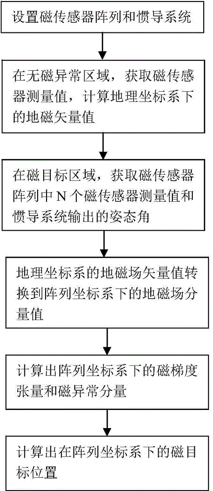
The invention belongs to the technical field of magnetic measurement, and particularly relates to a movable type location method based on magnetic gradient tensor and geomagnetic vector measurement. The method comprises the following steps: (S1) setting a magnetic sensor array and an inertial navigation system; (S2) in a nonmagnetic abnormal area, acquiring a measured value of a magnetic sensor and calculating a geomagnetic vector value in a geographic coordinate system; (S3) allowing a nonmagnetic moving device to move in a magnetic target area to acquire the measured value of the magnetic sensor and an attitude angle output by the inertial navigation system; (S4) calculating a geomagnetic field component value in an array coordinate system; (S5) calculating the magnetic gradient tensor and a magnetic abnormal component in the array coordinate system; and (S6) calculating the position of a magnetic target in the array coordinate system according to the magnetic gradient tensor and the magnetic abnormal component in the array coordinate system. The method disclosed by the invention can be used for achieving movable type real-time location, overcoming the requirement for immobility of the array in static location and acquiring the projection of a magnetic field in a magnetic sensor coordinate system more accurately by attitude conversion.

Description

technical field [0001] The invention belongs to the technical field of magnetic measurement, and in particular relates to a mobile positioning method based on magnetic gradient tensor and geomagnetic vector measurement. Background technique [0002] The geomagnetic field changes slowly, and its gradient tensor is negligible compared with the magnetic target anomaly. Three-axis magnetic sensors are widely used in the measurement of magnetic field components. Multiple magnetic sensors form an array to measure magnetic components and magnetic gradient tensors, so the magnetic sensor array can be used for magnetic target tracking and positioning. The basic principle is to treat the magnetic target as a magnetic dipole, and the magnetic gradient tensor and component of the magnetic dipole are related to the distance and the position of the space coordinate system. Then, the magnetic gradient tensor and component are measured by the magnetic sensor array, and the position of the ...

Claims


Application Information

Patent Timeline
Patent Type & Authority Applications(China)
IPC IPC(8): G01C21/08
CPCG01C21/08
Inventor 庞鸿锋朱学军万成彪张琦潘孟春陈棣湘罗诗途李季胡佳飞何赟泽
Owner NAT UNIV OF DEFENSE TECH
Why Eureka
Eureka Blog
Learn More