Turbine housing for exhaust turbocharger

A turbine housing and exhaust turbine technology, applied in the direction of machines/engines, mechanical equipment, engine components, etc., can solve the problems of inability to reduce heat, increase the weight of the overall exhaust turbocharger, etc., and achieve the effect of reducing heat

Inactive Publication Date: 2018-09-25
BORGWARNER INC
View PDF1 Cites 0 Cited by
  • Summary
  • Abstract
  • Description
  • Claims
  • Application Information

AI Technical Summary

Problems solved by technology

[0004] According to the information in DE102008011257A1, although this type of coolant arrangement should make it possible to simplify the design and make it possible to achieve a small increase in the weight of the turbine casing compared to other designs, the problem remains that it cannot be reduced heat input into the turbine housing, and instead the negative effects of this heat input can only be mitigated by the coolant unit
There are additional problems that, in particular for use in automobiles, the cooled turbine housing inevitably requires a relatively large installation space and above all increases the weight of the overall exhaust turbocharger

Method used


Image

  • Turbine housing for exhaust turbocharger
  • Turbine housing for exhaust turbocharger
  • Turbine housing for exhaust turbocharger

Examples


Embodiment Construction

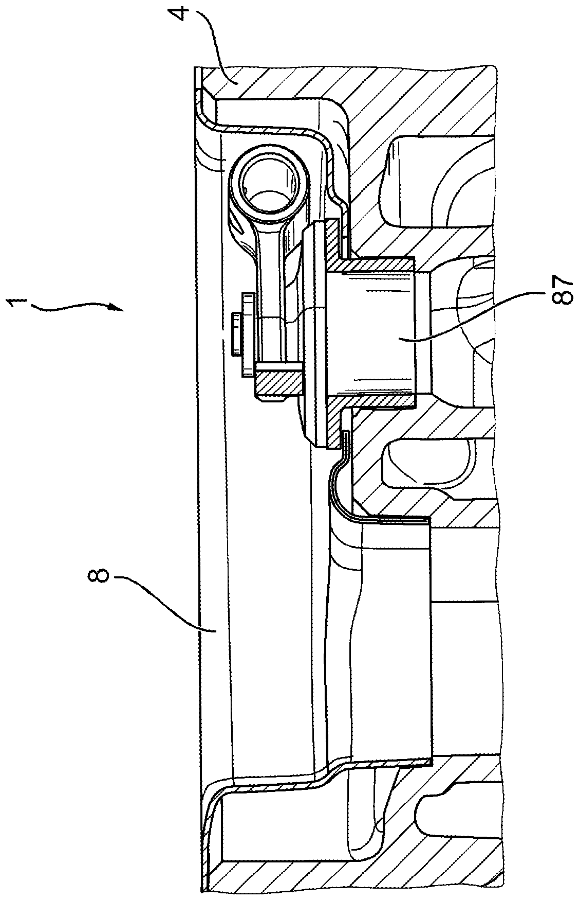
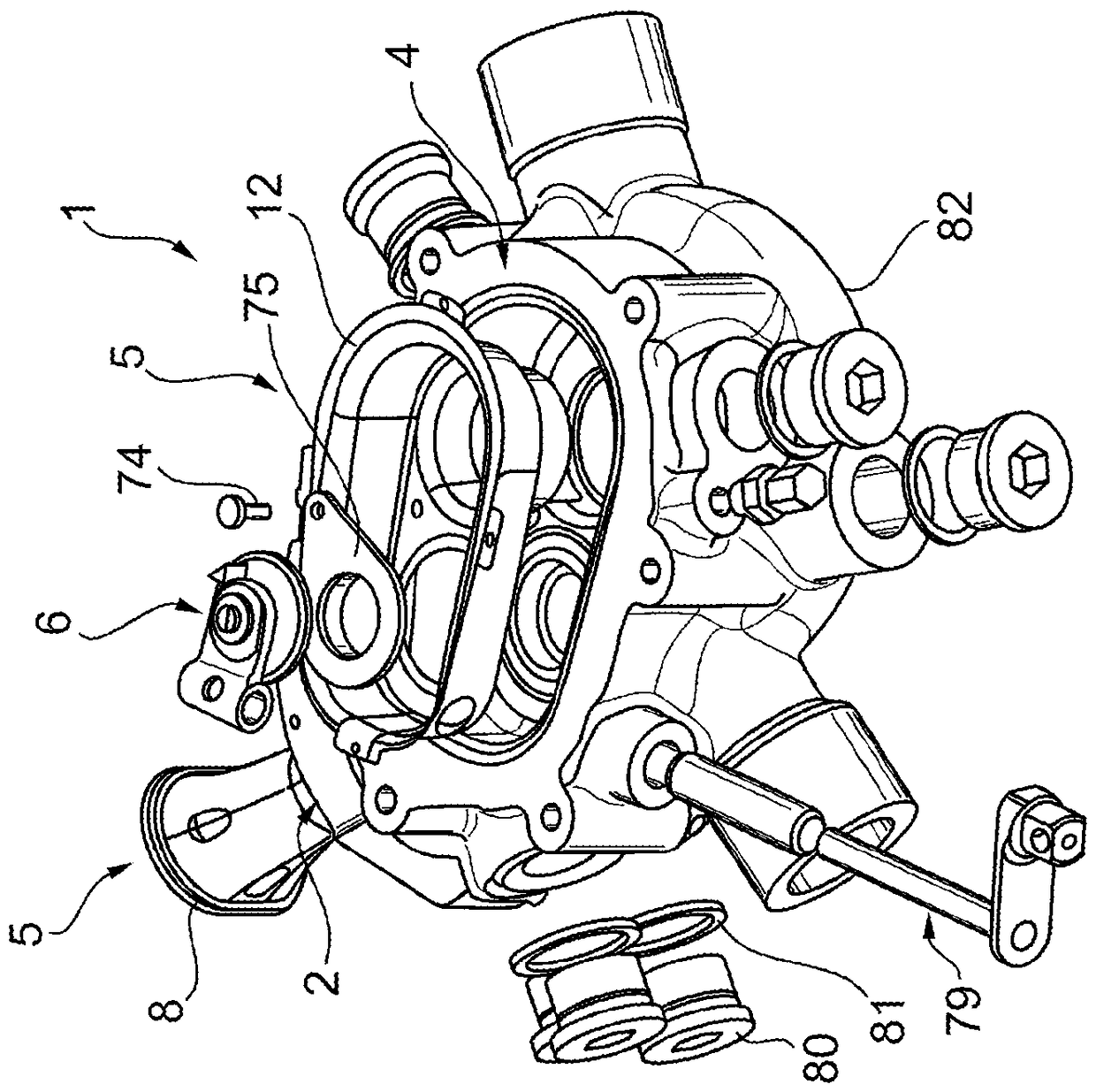
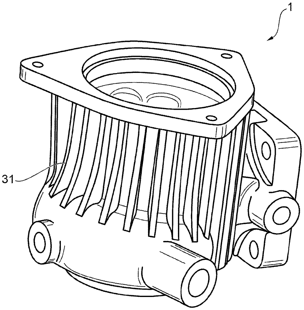
[0041] figure 1 A first embodiment of a turbine housing 1 according to the invention is shown, which has an inlet connection 2 and an outlet connection 4 . The spiral tube 3 is arranged between the inlet connection 2 and the outlet connection 4 . figure 1 Also shown is a wastegate arrangement 6 and an insulating device 5 , which is intended to reduce the heat input and which is arranged in this example in the region of the inlet connection 2 . exist figure 1 In the shown embodiment, this isolating means 5 is in the form of a sleeve or an insert part 8, as in figure 1 As can be seen in the drawing of , the spacer extends in this example in a slightly tapered design. This sleeve 8 extends from a fastening part 9 to a free end part 9', by means of which the sleeve 5 can be fixed to the inlet connection part 2, and the free end part extends in the inlet connection part 2. into the transition zone into the helical tube 3. In this example, the sleeve 8 is equipped with a spacer...


PUM


Abstract

The invention relates to a turbine housing (1) of an exhaust-gas turbocharger (62) having an inlet connection (2) adjoining a helical tube (3) and having an outlet A connection (4) featuring a spacer (5) for reducing heat input into the inlet connection (2), the coil (3) and / or the outlet connection (4) .

Description

[0001] This application is a divisional application of an invention application. The title of the invention of the parent case is the turbine casing of the exhaust turbocharger. The application date is October 22, 2010, and the application number is 201080047278.4 (international application number: PCT / US2010 / 053644). technical field [0002] The invention relates to a turbine housing for an exhaust-gas turbocharger. Background technique [0003] A turbine housing of this type is known from DE 10 2008 011 257 A1. In the case of such a turbine housing, shell elements are fastened to the outside of the turbine housing in order to form a hollow space in which the coolant is guided. [0004] According to the information in DE102008011257A1, although this type of coolant arrangement should make it possible to simplify the design and make it possible to achieve a small increase in the weight of the turbine casing compared to other designs, the problem remains that it cannot be re...

Claims


Application Information

Patent Timeline
Patent Type & Authority Patents(China)
IPC IPC(8): F02B39/00F01D25/24F01D25/08
CPCF01D9/026F01D17/105F01D25/12F01D25/145F02B37/183F02M26/05F02M26/06F05D2220/40F05D2230/90F05D2260/231F05D2300/121F05D2300/21F05D2300/5024F02M26/29Y02T10/12F04D29/403F04D29/5853
Inventor V.乔尔格T.科纳T.克瑞汀格S.韦斯S.伍艾斯特
Owner BORGWARNER INC
Why Eureka
Try Eureka