
A striker type cable cutting mechanism and its application method

A striker type, cable technology, applied in the field of mechanical structure, can solve the problem that the recovery unit and the discarding unit cannot be separated

Inactive Publication Date: 2016-01-13
SOUTH CHINA SEA INST OF OCEANOLOGY - CHINESE ACAD OF SCI
View PDF4 Cites 0 Cited by
  • Summary
  • Abstract
  • Description
  • Claims
  • Application Information

AI Technical Summary

Problems solved by technology

[0004] In some observation environments, the sensor needs to be installed in the discarding unit, and the measurement data is transmitted to the data acquisition system of the recovery unit through a cable. Develop a mechanism that can easily and effectively cut the cable connecting the discarding part and the recovery part, so that the discarding part and the recovery part of the submarine observation base station can be effectively separated by themselves

Method used


Image

  • A striker type cable cutting mechanism and its application method
  • A striker type cable cutting mechanism and its application method
  • A striker type cable cutting mechanism and its application method

Examples


Embodiment Construction

[0030] The present invention will be further described below in combination with specific embodiments. Wherein, the accompanying drawings are only for illustrative purposes, showing only schematic diagrams, rather than physical drawings, and should not be construed as limitations on this patent; in order to better illustrate the embodiments of the present invention, some parts of the accompanying drawings will be omitted, Enlargement or reduction does not represent the size of the actual product; for those skilled in the art, it is understandable that certain known structures and their descriptions in the drawings may be omitted.

[0031] In the drawings of the embodiments of the present invention, the same or similar symbols correspond to the same or similar components; , "vertical", "horizontal" and other indicated orientations or positional relationships are based on the orientations or positional relationships shown in the drawings, and are only for the convenience of desc...


PUM


Abstract

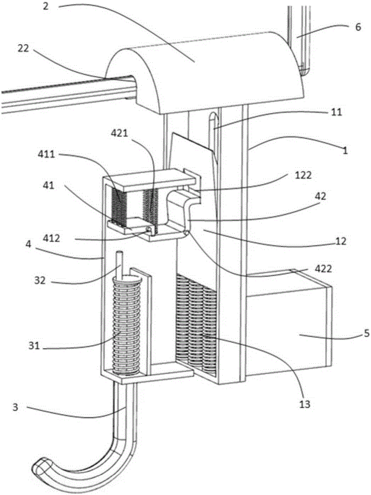
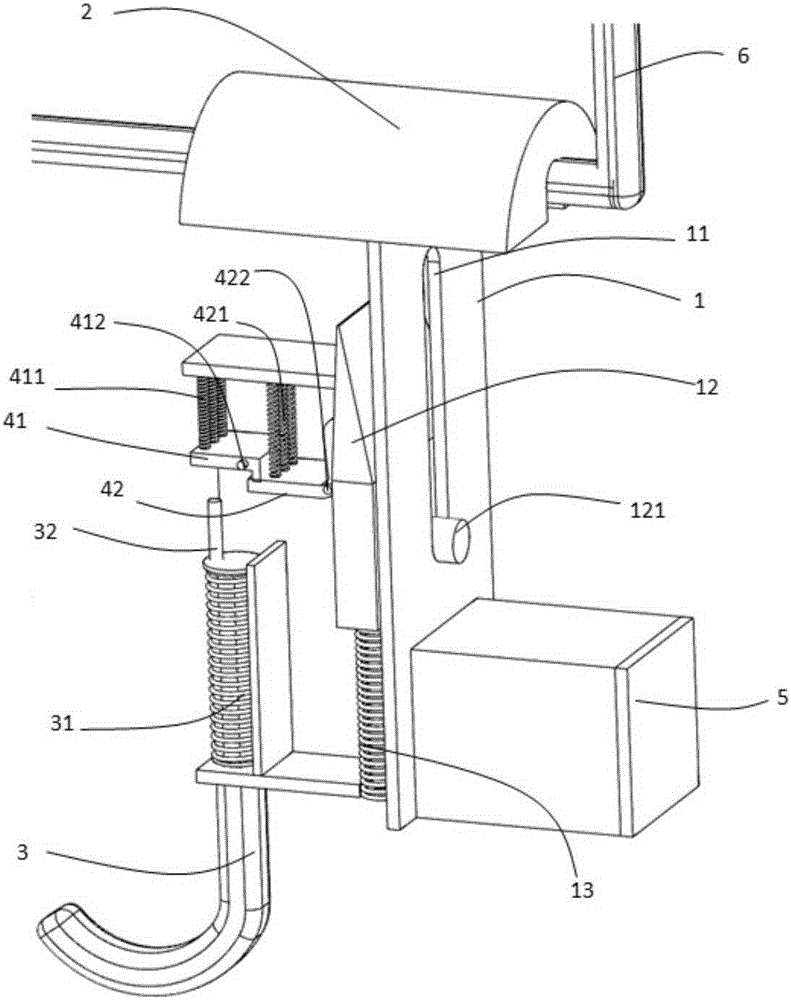
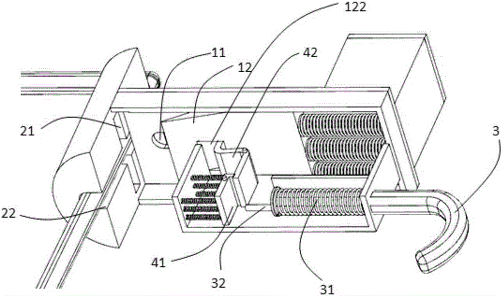
An impact pin-type cable severing mechanism consisting of a blade casing, a cable press plate, an ejection control casing, and a movable hook. Provided within the blade casing are a blade and a powerful compression spring below the blade. The ejection control casing is connected with the movable hook. A trigger piece and a blade latch are provided within the ejection control casing. In the impact pin-type cable severing mechanism, when the hook is taut, the blade latch within the ejection control casing is utilized to lock the blade, thus allowing the compression spring to remain in a compressed state, and when the hook is slack, the trigger piece is impacted by a rebound force to drive the blade latch into separating from the blade, and the compression spring is released to eject the blade to the cable press plate to sever a cable. Also disclosed is a use method for employing the cable severing mechanism in a seafloor observatory. The impact pin-type cable severing mechanism of the present invention is capable of effectively severing a cable in equipment when a relevant instruction is received, thus implementing equipment separation.

Description

technical field [0001] The invention relates to a mechanical structure, in particular to a mechanical structure for cable cutting and its use method in a seabed observation base station. Background technique [0002] From the time when humans were able to navigate to the present, due to technical and economic limitations, humans have often obtained their understanding of the ocean from ships through navigation, which determines that our exploration of the ocean is still at a superficial and one-sided stage. With the development of science and technology, and the urgent needs of different countries in terms of national security, economy, and strategy, human exploration of the ocean, especially the deep sea, has shown a blowout development. Submarine observation base stations (also known as submersible buoys) are the main means of deep sea observation, and the research on related technologies has become the key to the research and development of marine technicians today. [0...

Claims


Application Information

Patent Timeline
Patent Type & Authority Patents(China)
IPC IPC(8): B21F11/00
CPCB21F11/00
Inventor 孙兆华曹文熙
Owner SOUTH CHINA SEA INST OF OCEANOLOGY - CHINESE ACAD OF SCI
Learn More