
Optical measurement device for setting spraying path of spraying robot

An optical measuring equipment and spraying robot technology, which is applied in the directions of optical device exploration and spraying device, can solve the problems of lack of plate workpieces, complicated operation of robot offline programming software, and simulated spraying path, etc., to achieve easy operation, reduce human burden, improve The effect of spraying accuracy

Active Publication Date: 2015-04-22
成都思达特电器有限公司
View PDF9 Cites 7 Cited by
  • Summary
  • Abstract
  • Description
  • Claims
  • Application Information

AI Technical Summary

Problems solved by technology

However, the robot offline programming software used in practical applications is relatively complicated to operate, and requires an accurate CAD model or 3D model of the workpiece in order to simulate a more accurate spraying path
However, in the production environment where the accuracy of spraying paths is not high, such as furniture panels, these panel workpieces often do not have CAD or 3D models, so offline programming software cannot be used to simulate and generate spraying paths

Method used


Image

  • Optical measurement device for setting spraying path of spraying robot
  • Optical measurement device for setting spraying path of spraying robot
  • Optical measurement device for setting spraying path of spraying robot

Examples


Embodiment Construction

[0038] A detailed description will be given below of embodiments of the present invention. Although the present invention will be described and illustrated in conjunction with some specific embodiments, it should be noted that the present invention is not limited to these embodiments. On the contrary, any modification or equivalent replacement made to the present invention shall be included in the scope of the claims of the present invention.

[0039] In addition, in order to better illustrate the present invention, numerous specific details are given in the specific embodiments below. It will be understood by those skilled in the art that the present invention may be practiced without these specific details. In other instances, well-known methods, processes, components and circuits are not described in detail so as to highlight the gist of the present invention.

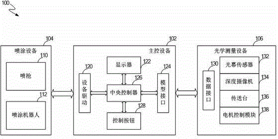
[0040] figure 1 Shown is an intelligent robotic painting system 100 according to an embodiment of the present ...


PUM


Abstract

The invention discloses an optical measurement device for setting a spraying path of a spraying robot. The optical measurement device comprises a conveying table, a light curtain sensor, a deep video camera and multiple data interfaces. The conveying table is used for conveying a sprayed workpiece from one end of the conveying table to the other end of the conveying table. The light curtain sensor comprises two groups of light curtain transmitters and receivers, and the two groups of light curtain transmitters and receivers are used for measuring and recording the projection view of the first side of the sprayed workpiece and the projection view of the second side of the sprayed workpiece respectively when the sprayed workpiece is conveyed through the conveying table. The deep video camera is used for measuring and recording the projection view of the third side of the sprayed workpiece according to the distance difference between the sprayed workpiece and the background of the conveying table. The projection view information of the first side, the second side and the third side is transmitted to a main control device through the multiple data interfaces, and the spraying path of the spraying robot is calculated through the main control device according to the projection views.

Description

technical field [0001] The invention relates to the field of spraying, in particular to an optical measuring device for setting the spraying path of a spraying robot. Background technique [0002] The use of spraying robots in the spraying industry can avoid artificial long-term exposure to toxic and harmful production environments. At present, the programming methods for spraying robots mainly include manual teaching method and offline programming method. In the manual teaching method, experienced workers operate the robot control handle to gradually move the position of the spray gun to complete the setting of the entire spray path. By recording and saving the parameter changes and positions of the end joints of the robot, the robot can repeat the original motion trajectory to realize automatic spraying. This method has relatively high labor costs. [0003] The off-line programming method requires the use of computer graphics technology to pre-generate the spraying work...

Claims


Application Information

Patent Timeline
Patent Type & Authority Applications(China)
IPC IPC(8): B05B13/04B05B15/10G01V8/20
CPCB05B13/04G01V8/20
Inventor 刘应德周义维龙望
Owner 成都思达特电器有限公司
Learn More