


Quick Research
Generate reliable direction feasibility study reports for your R&D in just a few steps.

Technical Q&A
Discover and master advanced knowledge NOW. Basics, ideas, possibilities, all at once.

Find Solutions
As an expert in R&D theories, this can generate solutions to your technical problems instantly.

Evaluate Feasibility
Analyze your overall solution with one click, know your potential R&D risks in advance.

Monitor Landscape
Get weekly tech updates, stay abreast of the latest tech innovations and key insights.
sliding parts
A technology for sliding parts and sliding surfaces, applied to engine components, engine seals, mechanical equipment, etc., to achieve the effects of preventing accumulation, improving lubrication performance, and improving sealing performance
- Summary
- Abstract
- Description
- Claims
- Application Information
AI Technical Summary
Problems solved by technology
Method used
Image

Examples
Embodiment 1
[0060] refer to Figure 1 to Figure 3 , the sliding member of Embodiment 1 of the present invention will be described.
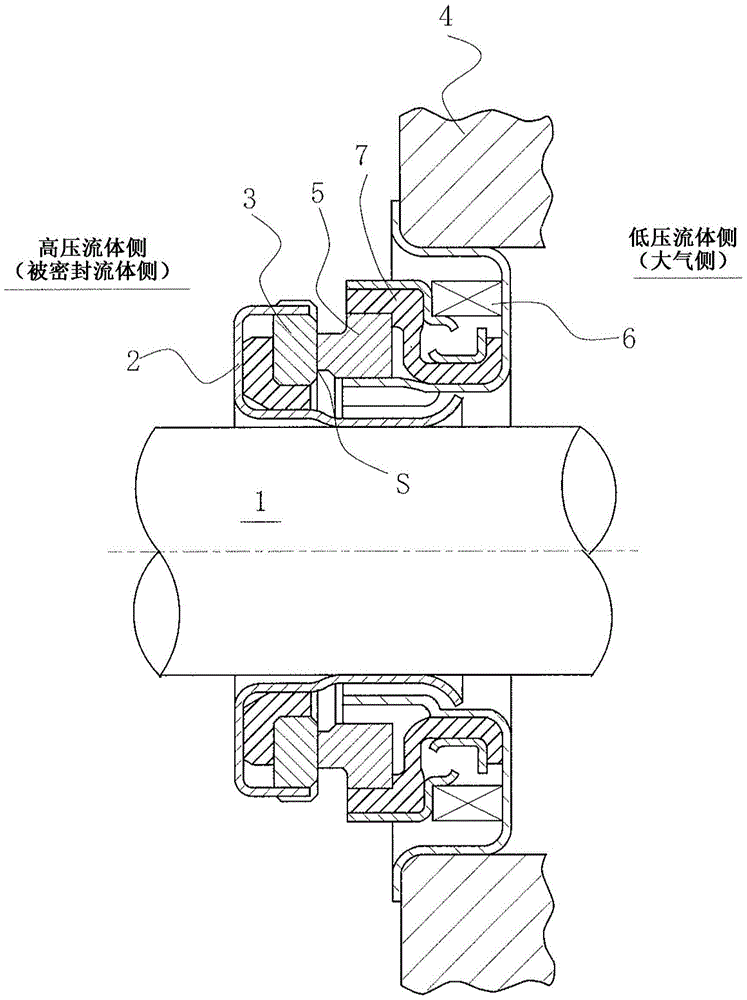
[0061] In addition, in the following embodiments, a mechanical seal as an example of a sliding member will be described as an example. In addition, the outer peripheral side of the sliding member constituting the mechanical seal will be described as the high-pressure fluid side (sealed fluid side), and the inner peripheral side will be described as the low-pressure fluid side (atmosphere side). However, the present invention is not limited thereto. It can also be applied to the case where the high-pressure fluid side and the low-pressure fluid side are reversed.
[0062] figure 1 It is a vertical cross-sectional view showing an example of a mechanical seal, and is a built-in mechanical seal that seals the sealed fluid on the high-pressure fluid side that leaks from the outer periphery of the sliding surface toward the inner periphery. An annular rotating ...
Embodiment 2
[0085] refer to Figure 4 and Figure 5 , the sliding member according to Embodiment 2 of the present invention will be described. The sliding part involved in embodiment 2 is different from the sliding part in embodiment 1 in the following aspects: a spiral groove 12 for discharging fluid to the high-pressure fluid side is additionally provided on the sliding surface, and other basic structures are the same as in embodiment 1, and the same Components are marked with the same reference numerals, and repeated explanations are omitted.
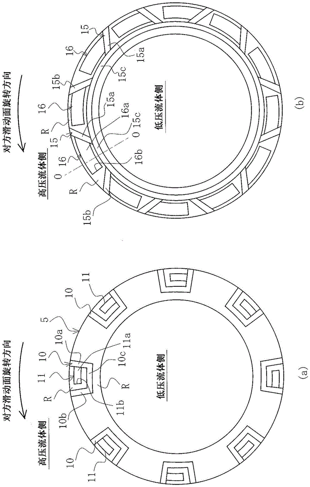
[0086] Figure 4 The fixing ring 5 shown in (a) is in figure 2 The sliding surface of the fixed ring 5 in (a) is additionally provided with a fixed ring with a spiral groove 12, on the sliding surface of the fixed ring 5, the outer side of the part surrounded by the fluid circulation groove 10 and the high-pressure fluid side, that is, the adjacent fluid Between the circulation grooves 10 and 10, there is provided a spiral groove 12 for dis...
Embodiment 3
[0095] refer to Figure 6 and Figure 7 , the sliding member according to Embodiment 3 of the present invention will be described.
[0096] The sliding member according to Embodiment 3 is the same as that in that the helical groove 13 that discharges the fluid to the high-pressure fluid side is provided to communicate with the low-pressure fluid side. Figure 4 and Figure 5 The embodiment differs from other basic structures with Figure 4 and Figure 5 Embodiment 2 is the same, and the same components are marked with the same reference numerals, and repeated descriptions are omitted.
[0097] Figure 6 The fixing ring 5 shown in (a) has the same Figure 4 (a) The same fluid circulation groove 10 and Rayleigh step mechanism 11, the spiral groove 13 provided outside the part surrounded by the fluid circulation groove 10 and the high pressure fluid side also communicates with the low pressure fluid side.
[0098] Additionally, for Figure 6 The fixed ring 5 shown in (b) ...
PUM
 Abstract
Description
Claims
Application Information
 - R&D Engineer
- R&D Manager
- IP Professional
- Industry Leading Data Capabilities
- Powerful AI technology
- Patent DNA Extraction
Browse by: Latest US Patents, China's latest patents, Technical Efficacy Thesaurus, Application Domain, Technology Topic, Popular Technical Reports.
© 2024 PatSnap. All rights reserved.Legal|Privacy policy|Modern Slavery Act Transparency Statement|Sitemap|About US| Contact US: help@patsnap.com