Clamping device used for clamping circular arc-shaped workpiece

A clamping device and arc-shaped technology, which is applied in the field of workpiece clamping and can solve the problem that the clamping jaws cannot fit together.

Inactive Publication Date: 2015-04-08
CHONGQING STRONG DUDLEY TECH DEV
View PDF0 Cites 5 Cited by
  • Summary
  • Abstract
  • Description
  • Claims
  • Application Information

AI Technical Summary

Problems solved by technology

[0004] The invention provides a clamping device for clamping arc-shaped workpieces to solve the problem that a clamping jaw cannot fit well with arc-shaped workpieces with different curvatures

Method used


Image

  • Clamping device used for clamping circular arc-shaped workpiece

Examples


Embodiment Construction

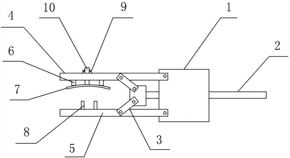
[0013] The reference signs in the drawings of the description include: base 1, control rod 2, drive rod 3, first jaw 4, second jaw 5, limit block 6, elastic piece 7, chuck 8, compression spring 9, slider10.

[0014] like figure 1 As shown, a clamping device for clamping a circular arc-shaped workpiece in this embodiment includes a base 1, a control rod 2, a compression spring 9, two driving rods 3 and two jaws for clamping a workpiece, The two jaws face the workpiece. The control rod 2 is slidably connected to the base 1 , and one end of the two driving rods 3 is respectively connected with the inner sides of the two jaws, and the other ends are connected with the control rod 2 . The two jaws are divided into a first jaw 4 and a second jaw 5 . The first jaw 4 is provided with a limit block 6, an elastic sheet 7 and a slide bar 10, and a through hole is provided on the first jaw 4, and one end of the slide bar 10 passes through the through hole, and the other end is connecte...


PUM


Abstract

The invention discloses a clamping device used for clamping a circular arc-shaped workpiece. The clamping device comprises a base, two clamping claws, a control rod and two driving rods, wherein the control rod is glidingly connected onto the base, one end of each of the two driving rods is respectively connected with the inner side of the two clamping claws, the other end of each of the two driving rods is respectively connected with the control rod, the two clamping claws are divided into the first clamping claw and a second clamping claw, two position limiting blocks, an elastic sheet and a slide rod are arranged on the first clamping claw, a through hole is formed in the first clamping claw, one end of the slide rod passes through the through hole, the other end of the slide rod is connected with the elastic sheet, the two position limiting blocks are respectively positioned at the inner side of the first clamping claw, the length of the elastic sheet is greater than the distance between the two position limiting blocks, the elastic sheet is glidingly connected onto the two position limiting blocks, and a clamping head positioned between the two position limiting blocks is arranged on the second clamping claw. The clamping device has the advantages that the elastic sheet arranged on the first clamping claw can be regulated according to the shape of the circular arc-shaped workpiece, the clamping head arranged on the second clamping claw can be used for conveniently regulating the vertical position of the slide rod, and the circular arc-shaped workpieces with different curvature can be conveniently clamped.

Description

technical field [0001] The invention belongs to the technical field of workpiece clamping. Background technique [0002] The workpiece grabbing mechanism is widely used in the field of mechanical processing. When the workpiece is roughly conveyed, the conveyor belt can be used for conveying; when the workpiece needs to be transported more accurately, the workpiece grasping mechanism must be used. [0003] The existing workpiece grabbing mechanism is two jaws hinged to each other. The clamping end of the jaws is used to clamp the workpiece, and the control end of the jaws is used to apply force. Although the above structure is used to clamp the workpiece, the structure is relatively simple, but When clamping arc-shaped workpieces, there are the following problems: due to the different curvatures of arc-shaped workpieces, the same jaw is used to clamp workpieces with different curvatures, and the jaws cannot fit well with the workpiece, making the grip The effect is not good....

Claims


Application Information

Patent Timeline
Patent Type & Authority Applications(China)
IPC IPC(8): B23Q7/04
CPCB23Q7/043
Inventor 丁小容
Owner CHONGQING STRONG DUDLEY TECH DEV
Why Eureka
Try Eureka