
A method, device and system for centralized monitoring of power supply

A technology of centralized monitoring and power supply, applied in general control system, control/regulation system, electrical program control, etc., to achieve the effect of reliable and stable monitoring system and low economic cost

Active Publication Date: 2017-08-29
CGN POWER CO LTD +1
View PDF7 Cites 0 Cited by
  • Summary
  • Abstract
  • Description
  • Claims
  • Application Information

AI Technical Summary

Problems solved by technology

[0003] However, the inventor found in the research and practice of the prior art that there is currently no device that can realize the unified monitoring of the operation of the power supply of different types of power supply equipment installed in different areas

Method used


Image

  • A method, device and system for centralized monitoring of power supply
  • A method, device and system for centralized monitoring of power supply
  • A method, device and system for centralized monitoring of power supply

Examples


Embodiment 1

[0019] Please refer to figure 1 , figure 1 It is a schematic diagram of the system structure of the embodiment of this application. Such as figure 1 As shown, a centralized power monitoring system is used to monitor the operating status of different types of power equipment in different areas, including:

[0020] The receiving switch optical transceiver 10 arranged in the monitoring room 1; and at least one receiving switching optical transceiver 20 and sending switching optical transceiver 21 arranged in the first area 2, the first area 2 is connected to the monitoring room 1.

[0021] And, the sending switching optical transceivers 30 are arranged in several second areas 3 , and the second areas 3 are connected with the first area 2 .

[0022] It is worth pointing out that it can be understood that both the first area 2 and the second area 3 are places where power supply equipment that needs centralized monitoring is placed. In this application, the first area 2 and the s...

Embodiment 2

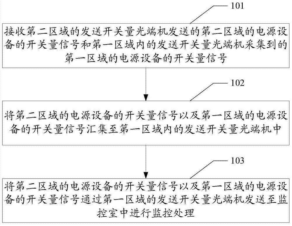
[0036] Please refer to figure 2 , figure 2 It is a flow chart of the method in the embodiment of the present application. Such as figure 2 As shown, a method for centralized power monitoring is used to monitor the operating conditions of different types of power devices in different areas, and may include the following steps:

[0037] 101. Receive the switching signal of the power supply equipment in the second area sent by the switching optical transceiver in the second area and the switching signal of the power supply equipment in the first area collected by the switching optical transceiver in the first area.

[0038] As described in Embodiment 1, there can be multiple second areas, and all the transmitting switch optical transceivers 30 in the second area 3 can send the switching signal of the power supply equipment 31 in the area to the receiving signal in the first area 2. In the switch optical transceiver 20. At the same time, the switching optical transceiver 21...

Embodiment 3

[0043] Please refer to image 3 , providing a centralized power supply monitoring device for monitoring the operating conditions of different types of power supply equipment in different areas of the first area and at least one second area, including:

[0044] The receiving unit 40 is used to receive at least one switching signal of the power supply equipment in the second area sent by the switching optical transceiver in the second area;

[0045] The collection unit 41 is used to collect the switching signal of the power supply equipment in the first area collected by the sending switch optical transceiver in the first area;

[0046] The converging unit 42 is used to collect the switch signal of the power supply equipment in the second area and the switch signal of the power supply equipment in the first area to the sending switch optical transceiver in the first area;

[0047] The sending unit 43 is used to send the switching signal of the power supply equipment in the seco...


PUM


Abstract

The invention relates to a concentrated power source control method, a device and a system. The system comprises a reception switching value optical transmitter and receiver arranged in a monitoring room, a reception switching value optical transmitter and receiver in a first region, a sending switching value optical transmitter and receiver in the first region and multiple sending switching value optical transmitter and receivers in a second region, wherein the reception switching value optical transmitter and receiver in the first region is connected with the sending switching value optical transmitter and receivers in the second region, acquired switching value signals of power source equipment in the second region are sent to the sending switching value optical transmitter and receiver in the first region, the sending switching value optical transmitter and receiver in the first region is connected with acquired switching value signals of power source equipment in the first region, the switching value signals of the power source equipment in the second region and the switching value signals of the power source equipment in the first region are gathered and sent to the monitoring room, the gathered signals are analyzed and processed by a warning device, and an instruction is carried out when the power source equipment is in an abnormal state. According to the system, concentrated monitoring management on multiple models of power source equipment in multiple regions can be realized. The system is reliable, stable, simple, practical and visual and further has property of low economic cost.

Description

technical field [0001] The present application relates to a centralized power monitoring method, device and system. Background technique [0002] The grid communication system is an essential and important system for the normal operation of nuclear power plants. The communication power supply is the core of the communication system. A stable and reliable communication power supply system is the key to ensure the safe and reliable operation of the grid communication system. If the power supply of the equipment is interrupted, the communication equipment will not be able to operate, resulting in the interruption of the communication circuit and the paralysis of the communication system, resulting in a great loss of economic and social benefits such as power grid accidents. Therefore, the background centralized monitoring of the communication power system is very necessary. The communication power supply equipment of Daya Bay Nuclear Power Plant and Ling'ao Nuclear Power Stati...

Claims


Application Information

Patent Timeline
Patent Type & Authority Patents(China)
IPC IPC(8): G05B19/418
CPCG05B19/41835Y02P90/02
Inventor 陈宏苏国彬黎天剑荣涛蒋振钢孙承武詹望余波许成君吕佳陈婉君梁雁斌王锦贤杨杰
Owner CGN POWER CO LTD
Learn More