Electronic expansion valve

An electronic expansion valve, valve body technology, applied in the direction of lift valve, valve details, valve device, etc., can solve the problem of high requirements for thermal stability of cylinder pressing pressure, achieve easy installation and disassembly, reduce labor intensity, and increase contact area effect

Active Publication Date: 2016-09-14
GREE ELECTRIC APPLIANCES INC
View PDF6 Cites 0 Cited by
  • Summary
  • Abstract
  • Description
  • Claims
  • Application Information

AI Technical Summary

Problems solved by technology

[0004] Aiming at the problem that traditional electronic expansion valves have high requirements on thermal stability and cylinder press-in pressure, the present invention provides an electronic expansion valve with easy installation and disassembly, and fastened magnets and rotor shafts.

Method used


Image

  • Electronic expansion valve
  • Electronic expansion valve
  • Electronic expansion valve

Examples


Embodiment Construction

[0030] In order to make the object, technical solution and advantages of the present invention clearer, the electronic expansion valve of the present invention will be further described in detail below with reference to the accompanying drawings and embodiments. It should be understood that the specific embodiments described here are only used to explain the present invention, not to limit the present invention.

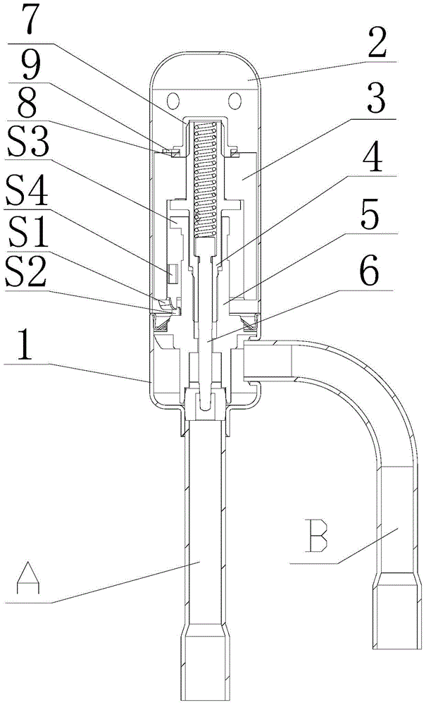
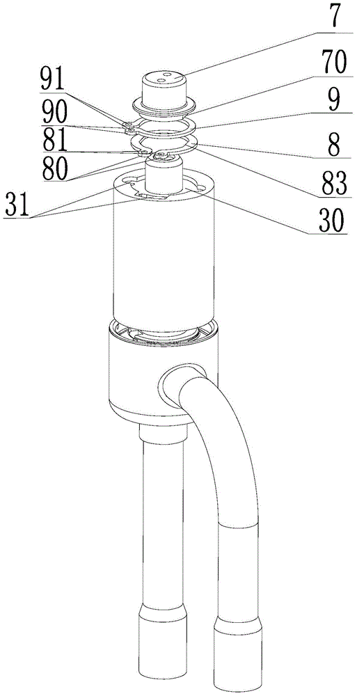
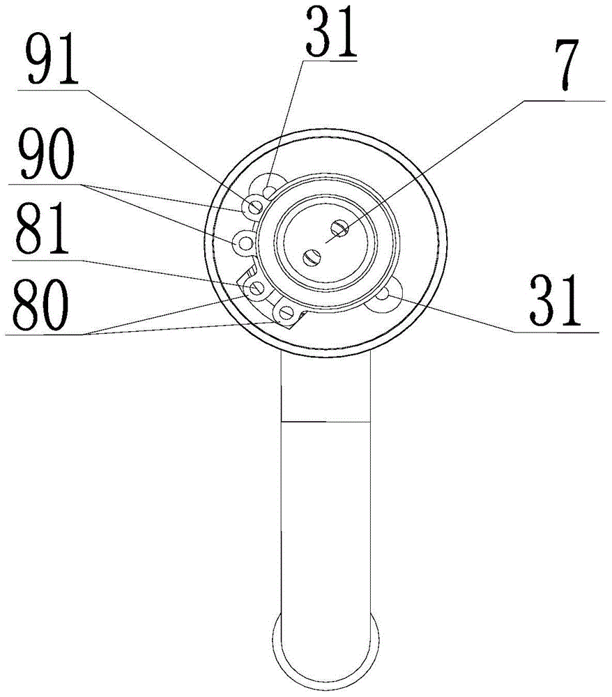
[0031] see figure 1 , figure 2 , image 3 The embodiment of the present invention provides an electronic expansion valve, which includes a valve body 1 and a casing 2. A rotatable magnet 3 is arranged inside the casing 2. The magnet 3 is fixedly connected to a rotor shaft 4. The magnet 3 is used to operate under the action of a rotating magnetic field. Drive the rotor shaft 4 to rotate synchronously, the rotor shaft 4 is screwed with the support part 5 fixed to the valve body 1, the rotor shaft 4 is provided with a valve needle 6, and the valve needle 6 is movably...


PUM


Abstract

The invention provides an electronic expansion valve. The electronic expansion valve comprises a valve body, a shell and a nut, wherein a rotatable magnet is arranged in the shell; the magnet is fixedly connected with a rotor shaft, and is used for driving the rotor shaft to rotate synchronously under the action of a rotary magnetic field; the rotor shaft is in threaded matching with a supporting component fixed to the opposite valve body; a valve needle is arranged in the rotor shaft and is movably arranged in the valve body along the axis of the valve body in a penetrating manner; the nut is in threaded matching with the upper end part of the rotor shaft; the magnet and the rotor shaft are fixedly connected. The nut is in threaded matching with the upper end part of the rotor shaft to realize fixed connection of the magnet and the rotor shaft; the valve is in threaded connection, is convenient to mount and disassemble, and has no requirement on thermal stability and cylinder press-in pressure, the equipment energy consumption and the labor intensity of operators are reduced, and the automation of mounting of the equipment is realized.

Description

technical field [0001] The invention relates to the technical field of fluid control components, in particular to an electronic expansion valve. Background technique [0002] As a control element, the electronic expansion valve plays a key role in the intelligence of the refrigeration system. The voltage applied by the coil controls the movement of the valve needle in the valve body, and adjusts the opening degree between it and the valve seat, thereby adjusting the flow rate of the expansion valve fluid. [0003] When the traditional electronic expansion valve is fixedly connected with the magnet and the rotor shaft, it is usually fitted and fixed by hot melting and snap-fitting of the engaging part, which requires high thermal stability and stable pressure of the cylinder when it is installed and fixed. sex. When the traditional electronic expansion valve controls the opening of the valve needle relative to the valve seat, it restricts the valve needle from approaching t...

Claims


Application Information

Patent Timeline
Patent Type & Authority Patents(China)
IPC IPC(8): F16K31/06F16K1/32
CPCF16K1/32F16K31/0655F25B41/31
Inventor 霍锦荣刘韬赵志军
Owner GREE ELECTRIC APPLIANCES INC
Why Eureka
Try Eureka