Energy-saving type low-torque butterfly valve

A low-torque, energy-saving technology, applied in the field of energy-saving low-torque butterfly valves, can solve problems such as damage, easy deformation of the butterfly plate, difficult valve switching, etc., to meet the needs of small torque, reduce opening torque, and improve service life. Effect

Inactive Publication Date: 2015-04-01
TIANJIN FSK FLOW CONTROL EQUIP
View PDF0 Cites 0 Cited by
  • Summary
  • Abstract
  • Description
  • Claims
  • Application Information

AI Technical Summary

Problems solved by technology

[0002] In the prior art, the seat and the butterfly plate of the traditional butterfly valve mostly use the inner plane fit of the cylinder. There are certain disadvantages in the matching method of this structure: the fit between the butterfly plate and the valve seat cannot be too tight, if the fit is too tight , the valve switch is very difficult. If you do not use force, it is difficult to open the valve or completely close the valve, and if you close the valve forcefully, the butterfly plate is easily deformed and damaged.
However, if the butterfly plate is not tightly matched with the valve seat, it is easy to cause leakage
[0003] Especially for the midline soft-sealing butterfly valve, customers have higher and higher requirements for the small torque and service life of the valve, and the existing valve design cannot meet customer needs

Method used


Image

  • Energy-saving type low-torque butterfly valve
  • Energy-saving type low-torque butterfly valve

Examples


Embodiment Construction

[0014] The present invention will be further described in detail below in conjunction with the drawings and specific embodiments. It should be understood that the specific embodiments described here are only used to explain the present invention, but not to limit the present invention.

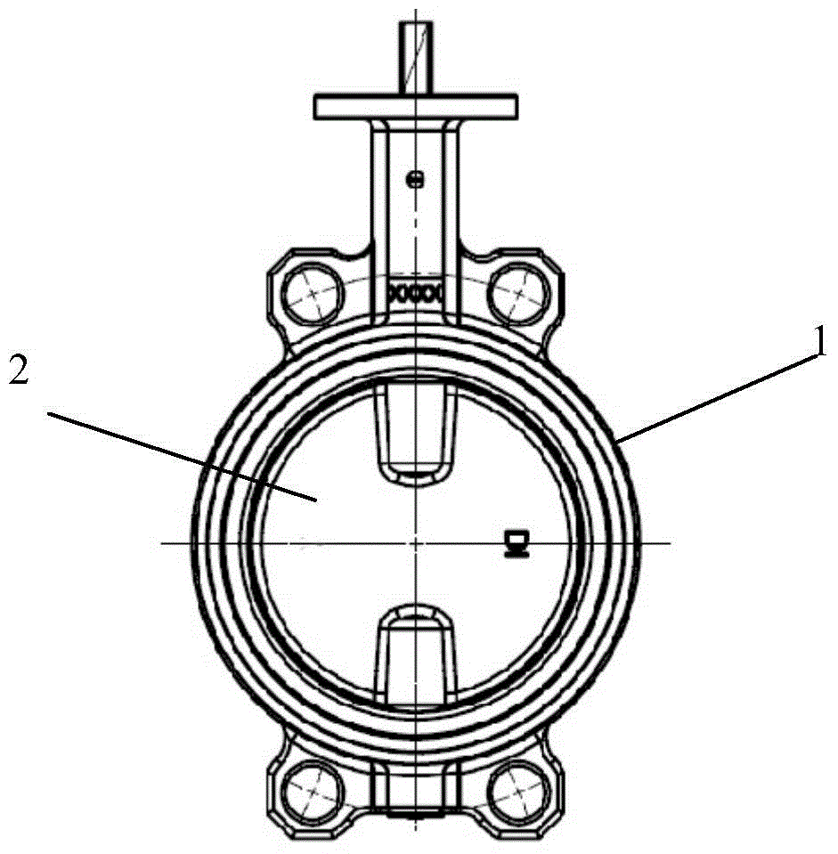
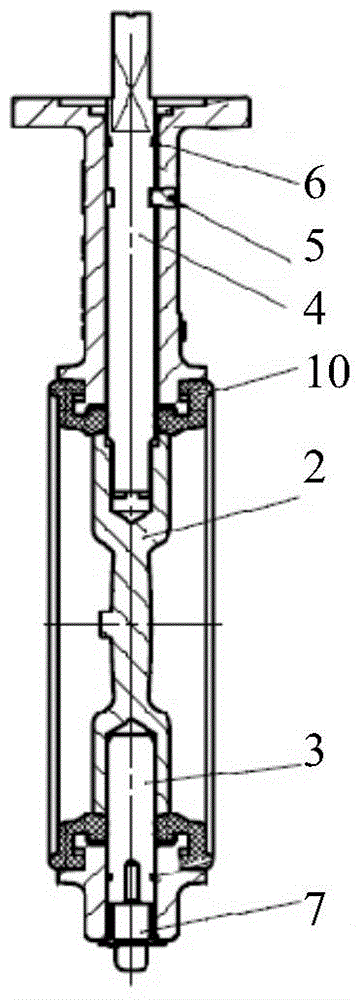
[0015] Such as figure 1 with 2 As shown, the energy-saving low-torque butterfly valve of the present invention includes a valve body 1, a valve seat 10, a valve plate 2, and a valve shaft. The inner wall surface of the valve seat is cylindrical, and the outer side surface of the valve plate is outer Convex spherical surface, the upper and lower ends of the valve seat and the valve plate are respectively formed with concave spherical dimples that match the spherical surface.

[0016] The invention adopts a unique spherical sealing structure, that is, the inner wall surface of the valve seat is a cylindrical structure, that is, the contact point between the inner wall surface of the valve seat and th...


PUM


Abstract

The invention discloses an energy-saving type low-torque butterfly valve which comprises a valve body, a valve base, a valve plate and a valve shaft, wherein the inner wall of the valve base is in a cylindrical shape; an outer side wall of the valve plate is a convex spherical surface; indent spherical slots matched with the spherical surface are respectively formed in the parts, corresponding to the upper end and the lower end of the valve plate, of the valve base. A unique spherical sealing type structure is adopted by the energy-saving type low-torque butterfly valve, the inner wall of the valve base is of a cylindrical structure, and the position, in contact with the valve plate, of the inner wall of the valve base is of the cylindrical structure; the peripheral surface of the valve plate is the spherical surface; the indent spherical slots are only respectively formed in the parts, corresponding to the upper end and the lower end of the valve plate, of the valve base; the sealing of the spherical surface is utilized to ensure the sealing property; the spherical surface is easily separated from the cylindrical structure, so that the starting torque is effectively reduced; the requirement of the customer on a small torque is met; the service life of the valve is effectively prolonged.

Description

Technical field [0001] The invention relates to the technical field of valves, in particular to an energy-saving low-torque butterfly valve. Background technique [0002] In the prior art, the valve seat and the butterfly plate of the traditional butterfly valve mostly adopt the inner plane of the cylinder. The matching method of this structure has certain disadvantages: the butterfly plate and the valve seat cannot be matched too tightly, if the fit is too tight , The valve switch is very difficult. If you don’t use force, it will be difficult to open the valve or completely close the valve. If you close the valve with force, the butterfly plate will easily deform and cause damage. However, if the butterfly plate and the valve seat are not closely matched, it is easy to cause leakage. [0003] Especially for the centerline soft-sealed butterfly valve, customers have higher and higher requirements for the valve's small torque and service life, and the existing valve design cannot ...

Claims


Application Information

Patent Timeline
Patent Type & Authority Applications(China)
IPC IPC(8): F16K1/22F16K1/32F16K31/44
CPCF16K1/22F16K1/226F16K1/32F16K31/44
Inventor 范全军何玉鹏王晓红
Owner TIANJIN FSK FLOW CONTROL EQUIP
Why Eureka
Try Eureka