Eureka AIR delivers breakthrough ideas for toughest innovation challenges, trusted by R&D personnel around the world.

Piston type internal combustion engine for quickly passing through dead point through magnetic boosting

A piston type, internal combustion engine technology, applied in mechanical equipment, machines/engines, etc., can solve the problems of unstable crankshaft rotation, different, unable to achieve work efficiency, etc., and achieve the effect of reducing energy loss

Inactive Publication Date: 2015-04-01
ZHEJIANG UNIV
View PDF7 Cites 2 Cited by
  • Summary
  • Abstract
  • Description
  • Claims
  • Application Information

AI Technical Summary

Problems solved by technology

In the prior art disclosed above, no matter the double crank type or combined piston type structure is adopted, all efforts are made to eliminate the dead point, and the power output form of the original engine is changed, so that the energy of fuel combustion in the cylinder cannot reach Original work efficiency
[0004] In the prior art, there is also a way of using an eccentric crank connecting rod mechanism to pass through the dead center. However, the use of an eccentric crank connecting rod mechanism will make the time of each stroke different, so that the crankshaft will not rotate smoothly, and the cylinder liner will Problems related to severe wear of the piston

Method used


Image

  • Piston type internal combustion engine for quickly passing through dead point through magnetic boosting
  • Piston type internal combustion engine for quickly passing through dead point through magnetic boosting

Examples


Embodiment Construction

[0016] The magnetic-assisted piston internal combustion engine passing through the dead center quickly will be further described in detail below in conjunction with the accompanying drawings and specific embodiments.

[0017] First of all, it should be noted that the present invention only improves part of the structure of the piston internal combustion engine in the prior art, so only the improved part of the structure is described in detail, and the existing structure without improvement is not repeated.

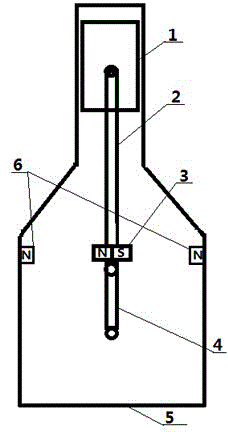
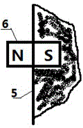
[0018] Such as figure 1 As shown, the structure of the piston-type internal combustion engine that is magnetically assisted to quickly pass through the dead center in this embodiment includes a cylinder 5, a piston 1, a connecting rod 2 and a crank 4, and the above-mentioned structure is no different from the prior art. The improvement is that magnets are respectively arranged on the inner walls of the connecting rod 2 and the cylinder 5, wherein a magnet-3 is provided on ...


PUM


Abstract

The invention discloses a piston type internal combustion engine for quickly passing through dead point through magnetic boosting. The piston type internal combustion engine comprises a cylinder, a piston, a connecting rod and a crank, wherein the end, hinged to the crank, of the connecting rod is provided with a magnet I; the connecting line of the N pole and the S pole of the magnet I is perpendicular to the connecting rod and is positioned in the plane of rotation of the crank; the inner wall of the cylinder is also provided with a pair of magnets II; when the connecting rod and the crank are collinear and the connecting rod is positioned at the position of an upper dead center, the pair of magnets II is positioned on the two sides of the magnet I and the connecting line of the pair of magnets II is collinear with the connecting line of the pole N and the pole S of the magnets I; when the polarities of the magnetic poles, on the side opposite to the magnet I, of the magnets II are the same and the crank starts to rotate from the upper dead center, the magnetic pole, on the same side as the linear speed direction of the crank, of the magnet I is reverse to the polarity of the magnetic pole of the oppositely arranged magnet II. The piston type internal combustion engine has a simple structure, and the relaxation time at the dead center is shortened, so that the purpose of improving the efficiency by shortening the energy consumption time as much as possible is achieved.

Description

technical field [0001] The invention relates to a piston-type internal combustion engine, in particular to a piston-type internal-combustion engine that rapidly passes through a dead point through magnetic force assistance. Background technique [0002] When the piston type internal combustion engine is ignited, the crank connecting rod is just on a straight line, that is, the piston is at the top dead center position, and at this time, the energy generated by the fuel combustion in the piston cylinder cannot be transferred to the crankshaft in time to be converted into power. Conventional piston internal combustion engines rely on the inertia of the crankshaft to make the crank pass the dead point, which takes a long time. During this period, the energy in the cylinder cannot be transmitted in time, resulting in energy loss, so the crank connecting rod mechanism can quickly pass the dead point. The position can be improved The power output of the internal combustion engine,...

Claims


Application Information

Patent Timeline
IPC IPC(8): F02B75/32
Inventor 熊树生田在鑫
Owner ZHEJIANG UNIV
Why Eureka
Eureka Blog
Learn More