
An automatic tab-bending device for battery side plates

A battery and side plate technology, applied in battery pack parts, circuits, electrical components, etc., can solve problems such as affecting the production efficiency of battery products, different strengths, affecting product quality, etc., to achieve a simple structure, reduce operators, The effect of low manufacturing cost

Active Publication Date: 2017-09-12
ZHUZHOU YINGDING AUTOMATION EQUIP TECH
View PDF8 Cites 0 Cited by
  • Summary
  • Abstract
  • Description
  • Claims
  • Application Information

AI Technical Summary

Problems solved by technology

[0002] In the lead-acid battery industry, the ears of the battery pole group are collectively referred to as "plate ears" or "pole ears". In the production of batteries, the casting and welding process is to reduce the problem of poor welding of the pole group such as "side plate falling off, side plate false welding" , the operator gently pinches the "plate lug" or "pole lug" of each pole group side plate inward at a certain angle when entering the pole group groove or into the fixture. Different, it is easy to cause the deformation of the frame under the tab, the active material is loose or even falls off and penetrates the separator to form a short circuit or micro short circuit, which seriously affects the product quality
[0003] At present, the semi-automatic shaping template pinching and bending negative plate lug shaping device used in machine casting and welding can only be operated manually, and the production efficiency is low, which seriously affects the production efficiency of large-scale production of battery products.

Method used


Image

  • An automatic tab-bending device for battery side plates
  • An automatic tab-bending device for battery side plates
  • An automatic tab-bending device for battery side plates

Examples


Embodiment Construction

[0021] In order to enable those skilled in the art to better understand the technical solutions of the present invention, the present invention will be further described in detail below in conjunction with the accompanying drawings and specific embodiments.

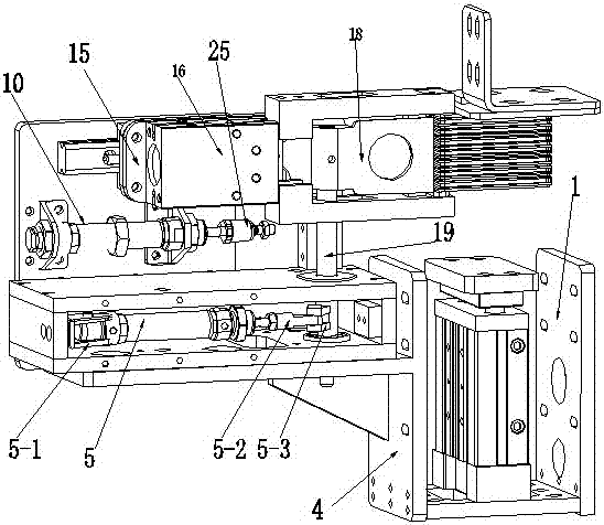
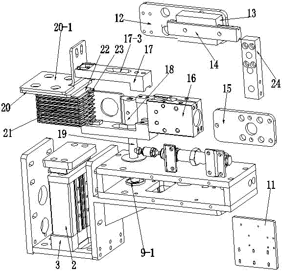
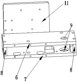
[0022] refer to figure 1 , figure 2 , image 3 and Figure 4 , an automatic tab-bending device for a side plate of a storage battery according to the present invention, comprising an L-shaped mounting seat 1, a lifting cylinder 2, a cylinder spacer 3, a T-shaped support plate 4, a cylinder 5, a fixing seat 5-1, and a connecting rod 5-2 , sleeve clamp 5-3, screw 5-4, upper plate 6, lower plate 7, side plate 8, through hole 9, bearing 9-1, sliding cylinder 10, mounting plate 11, A mounting plate 12, slider 13, Guide rail 14, B mounting plate 15, air finger 16, bead 17, pressure block 17-1, bump 17-2, waist-shaped hole 17-3, swing top piece 18, pawl 18-1, shaft 19, pressure plate 20. Platen seat 20-1, pole group 21, sid...


PUM


Abstract

The invention discloses an automatic tab-bending device for a battery side plate, which is characterized in that it mainly includes an L-shaped mounting seat, a lifting cylinder, a cylinder pad, a T-shaped support plate, a cylinder, a fixing seat, a connecting rod, a sleeve clip, and a screw , upper plate, lower plate, side plate, through hole, sliding cylinder, mounting plate, slider, guide rail, B mounting plate, air finger, pressure plate, bump, waist hole, shaft rod, swing top piece, the L The spacer is installed horizontally on the mounting base, the lifting cylinder is installed on the spacer, the T-shaped support plate is installed on the side of the L-shaped mounting seat, and the upper and lower plates, the cylinder, and the shaft are arranged successively above the T-shaped support plate. A mounting plate is installed behind the upper and lower plates, and guide rails and air fingers are arranged on the mounting plate. The pole group is arranged in the middle of the lifting cylinder and the pressing plate. The strength and angle of the tabs are consistent, ensuring that the side plates of each pole group are not damaged, which improves the quality and production efficiency of battery products.

Description

technical field [0001] The invention relates to storage battery production and assembly equipment, more specifically to a battery pole group side plate battery side plate automatic tab-bending device. Background technique [0002] In the lead-acid battery industry, the ears of the battery pole group are collectively referred to as "plate ears" or "pole ears". In the production of batteries, the casting and welding process is to reduce the problem of poor welding of the pole group such as "side plate falling off, side plate false welding" , the operator slightly pinches the "plate lug" or "pole lug" of each pole group side plate inward at a certain angle when entering the pole group groove or into the fixture. Inconsistency, it is easy to cause deformation of the frame under the tab, loose or even fall off of the active material and penetrate the separator to form a short circuit or micro short circuit, which seriously affects the product quality. [0003] At present, the se...

Claims


Application Information

Patent Timeline
Patent Type & Authority Patents(China)
IPC IPC(8): B21D5/04H01M2/26H01M50/533
CPCB21D5/04H01M50/541H01M50/531Y02E60/10
Inventor 郑圣泉黎派龙
Owner ZHUZHOU YINGDING AUTOMATION EQUIP TECH
Learn More