Automobile glass lifting switch
A glass lifting and switching technology, which is applied in the direction of electric switches, tumbler/rocker switch parts, electrical components, etc., can solve the problems of cost waste, poor compatibility of glass lifting switches, etc.
- Summary
- Abstract
- Description
- Claims
- Application Information
AI Technical Summary
Problems solved by technology
Method used
Image


Examples
Embodiment 1
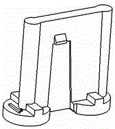
[0016] The glass lift switch for automobiles in this embodiment is provided with three gears: manual up, manual down, and stop. button, and a pair of push rods installed under both sides of the swing button; for the matching structure between the base, the shell, the circuit board, the swing button and the push rod, see the patent No. 201420287466.X, named "auto glass Lifting switch" utility model patent, no longer repeat them here.
[0017] Such as figure 1 As shown, the circuit board is provided with an input terminal and an output terminal, and the input terminal and the output terminal are connected by four parallel sub-lines, and each sub-line corresponds to a glass lifting function, for example, the sub-line where the resistor R1 is located Corresponding to the function of manually lowering the door glass (see Table 1 for details), each sub-line is equipped with a light touch switch (K1~K4), and the resistance value of each sub-line is different; the four sub-lines The...
Embodiment 2
[0024] Different from Embodiment 1, this embodiment is provided with five gears: manual ascending, automatic ascending, manual descending, automatic descending, and stop. According to the principle of this case, when the push rod is pressed down under the action of the swing button, the two tact switches below the push rod are triggered sequentially, so that the two push rods can provide four trigger signals and One stop signal (when the pendulum is in the central position), thus realizing the control of five gears.
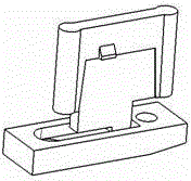
[0025] In this embodiment, the tact switch is composed of two contacts on the circuit board and a conductive rubber pad located between the push rod and the circuit board, and the two contacts are respectively connected to the same sub-circuit. At the two ends, the conductive rubber pad is located above the two contacts. The bottom surface of the push rod is a plane (such as figure 2 shown), the strokes of the two tact switches in the same group corresponding ...
Embodiment 3
[0027] Different from Embodiments 1 and 2, this embodiment is provided with four gears: manual ascending, automatic ascending, manual descending, and stop. The structure of the ejector rod and the tact switch of this embodiment is the same as that of Embodiment 2, but the resistor R2 in the sub-circuit is not welded, so that when the ejector rod is pressed down under the action of the pendulum button, the two push rods below the ejector rod are sequentially triggered. Lightly touch the switch, so that the two push rods can provide three trigger signals and one stop signal (when the pendulum is in the central position) under the action of the pendulum knob, so as to realize the control of four gears. Since the resistor R2 is not welded, when the tact switch connects the sub-circuit where the resistor R2 is located (that is, when the two tact switches of the sub-circuit where R1 and R2 are located are triggered at the same time), the resistance value between the input terminal an...
PUM
 Abstract
Description
Claims
Application Information
 - R&D
- Intellectual Property
- Life Sciences
- Materials
- Tech Scout
- Unparalleled Data Quality
- Higher Quality Content
- 60% Fewer Hallucinations
Browse by: Latest US Patents, China's latest patents, Technical Efficacy Thesaurus, Application Domain, Technology Topic, Popular Technical Reports.
© 2025 PatSnap. All rights reserved.Legal|Privacy policy|Modern Slavery Act Transparency Statement|Sitemap|About US| Contact US: help@patsnap.com