
Light module and preparing method thereof

An optical module and light outlet technology, applied in the directions of light guides, optics, optical components, etc., can solve the problems of complex steps, low success rate, and increase in the production cost of optical modules, and achieve the effect of reducing production costs and reducing process difficulty.

Active Publication Date: 2015-03-25
旭创科技有限公司
View PDF4 Cites 13 Cited by
  • Summary
  • Abstract
  • Description
  • Claims
  • Application Information

AI Technical Summary

Problems solved by technology

However, this kind of processing technology is difficult, the steps are complicated and the success rate is low, which leads to the increase of the production cost of the optical module and reduces the competitiveness of the product

Method used


Image

  • Light module and preparing method thereof
  • Light module and preparing method thereof
  • Light module and preparing method thereof

Examples


Embodiment Construction

[0024] The application will be described in detail below in conjunction with specific implementations shown in the accompanying drawings. However, these implementations do not limit the present application, and any structural, method, or functional changes made by those skilled in the art based on these implementations are included in the protection scope of the present application.

[0025] In each drawing of the present application, some dimensions of structures or parts are exaggerated relative to other structures or parts for convenience of illustration, and therefore, are only used to illustrate the basic structure of the subject matter of the present application.

[0026] In addition, terms used herein such as "upper", "above", "under", "below", etc. to express relative positions in space are for convenience of description to describe a unit or feature as shown in the drawings relative to A relationship to another cell or feature. The terms of spatial relative position ...


PUM


Abstract

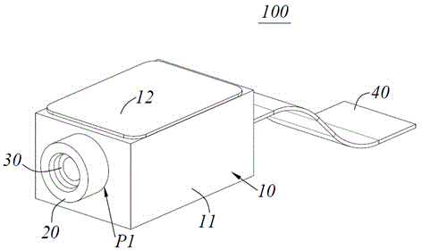
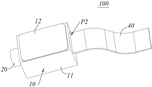
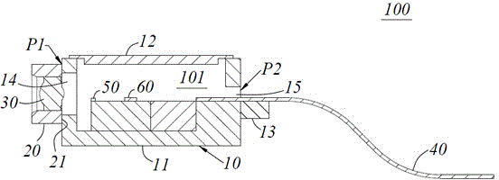
The invention discloses a light module and a preparing method thereof. The light module comprises a metal shell body and an optical component packaged in the metal shell body. A light outlet corresponding to the optical component is formed in the metal shell body. The light module further comprises a metal sleeve which is connected to the light outlet in a ring mode. A lens is arranged in the metal sleeve. According to the technical scheme, the lens is arranged in the metal sleeve, by connecting of the metal sleeve and the metal shell body, corresponding of the lens and the light outlet in the metal shell body is achieved, the fact that the lens can allow passing of a light path of the light module is guaranteed, meanwhile, the metal sleeve and the metal shell body can be fixedly connected in a conventional welding mode, technology difficulty is lowered, and then the production cost of the light module is lowered.

Description

technical field [0001] The invention belongs to the technical field of manufacturing optical communication components, and in particular relates to an optical module and a manufacturing method thereof. Background technique [0002] In the manufacturing process of optical modules, it is usually necessary to hermetically package the photoelectric components and chips in the optical module to provide good airtight protection for the internal components and chips, which is conducive to ensuring stable performance of the device. [0003] In the existing optical module, the metal casing usually has a light outlet for the optical path of the optical module to pass through. In order to ensure the airtight performance of the optical module and the light outlet for the optical path to pass through, a sintering method is usually used to A transparent medium window (such as a glass window cover) is fixed on the metal shell around the light outlet. However, this processing technique is ...

Claims


Application Information

Patent Timeline
IPC IPC(8): G02B6/42G02B6/32
CPCG02B6/4204
Inventor 孙雨舟于登群常江王祥忠
Owner 旭创科技有限公司
Learn More