
Rotation handle

A technology for turning handles and handles, which is applied in the direction of leaf handles, leaf handles, door/window accessories, etc. It can solve the problems of easy rust, loss of function of springs, and poor reliability of handle performance, etc., to achieve strong performance, The effect of strong reliability

Pending Publication Date: 2015-03-25
CHONGQING OFAN DOOR IND
View PDF7 Cites 0 Cited by
  • Summary
  • Abstract
  • Description
  • Claims
  • Application Information

AI Technical Summary

Problems solved by technology

[0004] Chinese patent CN103883162 uses a spring for elastic buffering, but the spring is a component with poor performance. If used for a long time, the spring is prone to rust and eventually loses its function, which makes the reliability of the entire handle poor.

Method used


Image

  • Rotation handle
  • Rotation handle

Examples


Embodiment Construction

[0021] The present invention will be described in further detail below by means of specific embodiments:

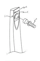
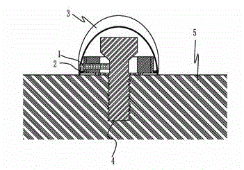
[0022] The reference signs in the drawings of the specification include: jacking screw 1 , limit ring 2 , handle body 3 , positioning screw 4 , and door body 5 .

[0023] Such as figure 1 As shown, the rotating handle of the present invention includes a handle body 3 and a set screw 4, wherein the set screw 4 is fixedly connected with the door body 5, and the set screw 4 includes an enlarged head and a slender stem; the inside of the handle body 3 is an inner cavity, the head of the set screw 4 penetrates into the inner cavity, the end face of the handle body 3 connected with the set screw 4 is provided with a notch for the set screw 4 to penetrate, and a limit ring 2 is provided at the notch , The middle part of the limit ring 2 is provided with a through hole for the head of the positioning screw 4 to penetrate.

[0024] figure 1 Only the upper part of the handle bod...


PUM


Abstract

The invention relates to a door plank machining instrument, in particular to a rotation handle. The rotation handle comprises a handle body and a positioning screw, wherein the positioning screw is fixedly connected with a door body and comprises an expanded head and a slim rod, the inside of the handle body is an inner cavity, the head of the positioning screw is inserted into the inner cavity, and the end face of the handle body connected with the positioning screw is provided with a notch for the positioning screw to insert in. A limit ring is arranged at the notch, the middle of the limit ring is provided with a through hole allowing the head of the positioning screw to insert, and a chamfer is reserved between the head and the rod of the positioning screw. The rotation handle further comprises a jackscrew, the jackscrew extends to the rod of the positioning screw in the rotation handle from the outside of the handle body, and the limit ring and the handle body are provided with a screw allowing the jackscrew to insert in. The rotation handle overcomes the defect of poor reliability in the prior art and is rotatable and provided with a buffer space.

Description

technical field [0001] The invention relates to an accessory of a door body, in particular to a handle matched with a rotating door. Background technique [0002] For doors with external handles, the handles are usually fixed to the door body by screws. In order to achieve a stable connection, the gap between the connecting parts is small (mostly interference fit). If the door is opened with excessive force, there is no buffer space between the parts, and it is easy to loosen due to local stress concentration. [0003] In order to solve the above problems, Chinese patent CN103883162 discloses a door handle, which includes a bottom case and a pull rod. A sliding guide rail is arranged on the bottom case, and limit blocks are arranged at both ends of the slide guide rail. The length of the pull rod is smaller than the length of the slide guide rail. Both ends of the pull rod are rotatably connected to a connecting rod, and the other end of the connecting rod is rotatably conn...

Claims


Application Information

Patent Timeline
IPC IPC(8): E05B1/00
Inventor 刘侃
Owner CHONGQING OFAN DOOR IND
Learn More