
Assembly type truss formwork support

A formwork support and assembly technology, which is applied in the direction of formwork/formwork/work frame, connectors of formwork/formwork/work frame, and on-site preparation of building components, which can solve the problem of web eccentricity and large gap between assembly nodes , large vertical deflection, and many assembly times, etc., to reduce the influence of web member eccentricity and assembly gap, reduce vertical deflection, and ensure the rigidity of the truss

Active Publication Date: 2015-03-25
山东高速德建集团有限公司
View PDF4 Cites 4 Cited by
  • Summary
  • Abstract
  • Description
  • Claims
  • Application Information

AI Technical Summary

Problems solved by technology

The patent is composed of upper chord, lower chord, straight web, diagonal web, pre-compressed steel bars and assembled nodes. According to experiments, the connection method of the above patent is single-rod node connection, and the compression web and lower chord The connection has been flattened, the assembly times are many, the truss rigidity is low, the gap between the eccentricity of the web member and the assembly node is too large, the vertical deflection is large, and the bearing capacity is low

Method used


Image

  • Assembly type truss formwork support
  • Assembly type truss formwork support
  • Assembly type truss formwork support

Examples


Embodiment 1

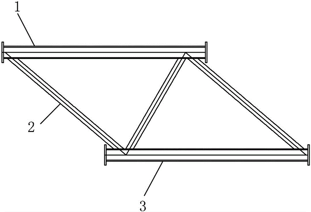
[0031] As shown in the figure: 1-8: the truss is changed from the original single-bar assembly to the shaped truss unit with end plates connected by bolts 5 to connect the joints, 1-meter single-bar unit 21, type I truss unit (1 meter) 20 and Type II truss units (2m) 18, end rods 19, the upper and lower chords 1, 3 of each shaped truss unit are connected to the diagonal support 2 by welding, the ends are end plates 4 with bolt holes, and the truss units are connected by bolts 5, After assembly, a truss with a span of 6 meters can be formed, and a vertical support 7 is added to the end rods 19 at both ends of the truss to form an assembled truss formwork support; the truss unit node at the end of the truss with different spans is A node 10, and the vertical support 7 The connection with the end bar is the B node 9, and when the distance from the A node to the B node is 150mm, another vertical support is added at the A node 10.

[0032] The shaped truss unit includes Type I trus...

Embodiment 2

[0039] The difference from Embodiment 1 is that a type II truss unit (2 meters) and end rods form a truss with a span of 4M.

Embodiment 3

[0041] The difference from Embodiment 1 is that a type II truss unit (2 meters), a type I truss unit (1 meter) and end rods form a truss with a span of 5M.


PUM


Abstract

The invention provides an assembly type truss formwork support, belongs to the technical field of construction, and particularly relates to a truss and a support which are used for construction. The truss is obtained by assembling one-meter single-rod units, I type truss units (one meter), II type truss units (two meters) and end rods through shaping truss units with end plates by means of bolt connection joints instead of assembling existing single rods. Upper chords, lower chords and inclined supports of all the truss units are connected through welding, the end plates with bolt holes are adopted for the ends of the truss units, the truss units are connected through bolts, different spans of trusses can be formed after assembly, the end rods are additionally arranged at the ends of the assembly truss, vertical supports are additionally arranged on the end rods, and the assembly type truss formwork support is formed. The assembly type truss formwork support is obtained by connecting and assembling the end plate shaping truss units with the bolt holes through the bolts, the number of splicing times is reduced, and therefore the rigidity of the trusses is ensured, web member eccentric influences and assembly gaps are reduced, the vertical deflection is reduced, and the bearing capacity is improved. All the truss units are assembled through the connection plate joints with the bolt holes, and different spans of trusses can be obtained after assembly.

Description

technical field [0001] The invention belongs to the field of building technology, and in particular relates to a building truss and support. Background technique [0002] The closest existing technology to the present invention is the patent number 201020195386.3, the patent name is: assembled formwork truss support, and the patentees are: Shandong Dejian Group Co., Ltd., Shandong Liaojian Group Co., Ltd. The patent is composed of upper chord, lower chord, straight web, diagonal web, pre-compressed steel bars and assembled nodes. According to experiments, the connection method of the above patent is single-rod node connection, and the compression web and lower chord The connection has been flattened, the assembly times are high, the truss rigidity is low, the gap between the eccentricity of the web member and the assembly node is too large, the vertical deflection is large, and the bearing capacity is low. Contents of the invention [0003] The purpose of the present inve...

Claims


Application Information

Patent Timeline
Patent Type & Authority Applications(China)
IPC IPC(8): E04G17/00E04G11/48
Inventor 靳海洋胡兆文唐志勃靳立晓
Owner 山东高速德建集团有限公司
Learn More