
A sand suction air lifting device

A technology of pneumatic lifting device and sand suction pipe, which is applied in the direction of earth mover/shovel, mechanically driven excavator/dredger, construction, etc. It can solve the problems of lifting height limitation and achieve the effect of convenient and efficient cleaning

Inactive Publication Date: 2017-03-15
重庆长航东风船舶工业有限公司
View PDF3 Cites 0 Cited by
  • Summary
  • Abstract
  • Description
  • Claims
  • Application Information

AI Technical Summary

Problems solved by technology

[0003] The existing sand suction equipment can only lift loose river sand in river sand silted waters, and due to the limitation of vacuum degree, the lifting height is also limited

Method used


Image

  • A sand suction air lifting device

Examples


Embodiment Construction

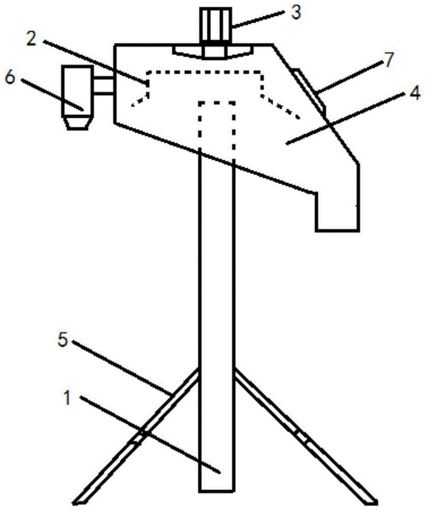
[0018] The invention discloses a sand suction pneumatic lifting device, which can conveniently and efficiently clean up deposited river sand.

[0019] The technical solutions in the embodiments of the present invention will be clearly and completely described below in conjunction with the accompanying drawings in the embodiments of the present invention. Obviously, the described embodiments are only some, not all, embodiments of the present invention. Based on the embodiments of the present invention, all other embodiments obtained by persons of ordinary skill in the art without making creative efforts fall within the protection scope of the present invention.

[0020] Such as figure 1 as shown, figure 1 Schematic diagram of the structure of the sand-absorbing pneumatic lifting device provided by the present invention.

[0021] The invention provides a sand suction pneumatic lifting device, which includes a sand suction pipe 1, the upper end of the sand suction pipe 1 extend...


PUM


Abstract

The invention provides a sand suction air-lift device. The sand suction air-lift device comprises a sand suction tube, wherein the upper end of the sand suction tube extends into a sand discharging chamber; the upper portion of an extending end of the sand suction tube in the sand discharging chamber is transversely provided with a baffle which stops muddy sand from entering a fan; and the fan is arranged above the baffle. When silted river sand is required to be cleaned, the lower end of the sand suction tube extends in the silted river sand, the fan is started, the air pressure in the sand discharging chamber and the air pressure in the sand suction tube are reduced, the silted river which is in contact with the lower portion of the sand suction tube is sucked in the sand suction tube, after being sucked in the sand discharging chamber, the river sand in the sand suction tube impacts the baffle, then is discharged out of the sand discharging chamber and is collected, the silted river sand is cleaned, the height of the sand suction tube can be adjusted according to operation height, the inner air pressure of the sand suction air-lift device is reduced with the aid of the fan, working requirements can be met, and the baffle can effectively prevent the river sand from entering the fan. By the sand suction air-lift device, the silted river sand can be cleaned conveniently and efficiently.

Description

technical field [0001] The invention relates to the technical field of sand suction equipment, and more specifically, to a sand suction pneumatic lifting device. Background technique [0002] In many rivers and lakes, due to long-term accumulation, there are a large amount of silt and river sand inside. On the one hand, these silt and river sand have brought damage to the environment; It hinders the normal development of river and lake operations. Therefore, in many cases, it is necessary to clean up the silt or river sand inside the river and lake. [0003] Existing sand suction equipment can only lift loose river sand in river sand silted waters, and due to the limitation of vacuum degree, the lifting height is also limited. [0004] Therefore, how to clean up the deposited river sand conveniently and efficiently is a problem to be solved urgently by those skilled in the art. Contents of the invention [0005] In view of this, the present invention provides a sand-abso...

Claims


Application Information

Patent Timeline
Patent Type & Authority Patents(China)
IPC IPC(8): E02F5/28E02F3/88E02F3/90
Inventor 钟守道陈道凯肖祥鹏赵紫微
Owner 重庆长航东风船舶工业有限公司
Learn More