
A pipe feeding device

A feeding device and conduit technology, applied in the direction of transportation and packaging, conveyor objects, etc., can solve the problems of not considering the accuracy of the silo, not disclosing the silo and rack, affecting the feeding efficiency of the conduit, etc., to achieve saving Positioning time, improving the quickness of replacement, and improving the effect of feeding efficiency

Active Publication Date: 2016-08-24
MAIDER MEDICAL IND EQUIP
View PDF5 Cites 0 Cited by
  • Summary
  • Abstract
  • Description
  • Claims
  • Application Information

AI Technical Summary

Problems solved by technology

However, the above-mentioned patent does not disclose how to realize the detachment between the silo and the frame, and because the linear motor drive, the detection of the position sensor and the gripping of the manipulator all pose great challenges to the accuracy of the installation position of the silo. High requirements, the above patent obviously did not take into account the accuracy of the silo installation, therefore, in the actual installation of the silo, the accuracy of the silo will be low, and the replacement of the silo will be slow, thus affecting the feeding efficiency of the conduit

Method used


Image

  • A pipe feeding device
  • A pipe feeding device
  • A pipe feeding device

Examples


Embodiment Construction

[0023] The following are specific embodiments of the present invention and in conjunction with the accompanying drawings, the technical solutions of the present invention are further described, but the present invention is not limited to these embodiments.

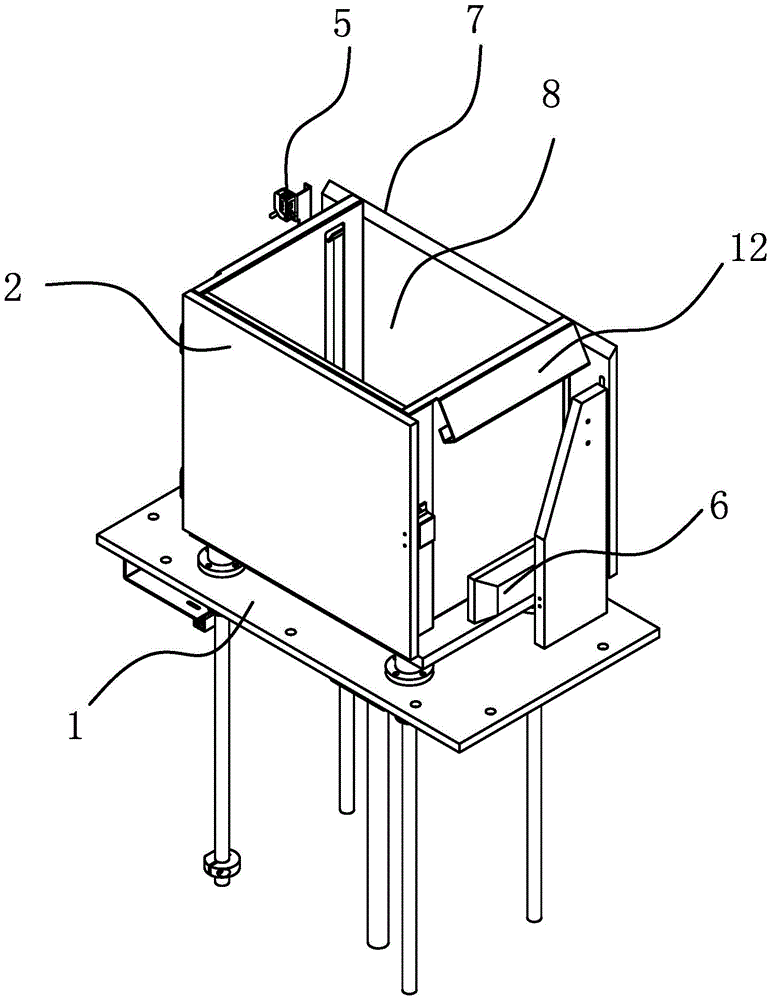
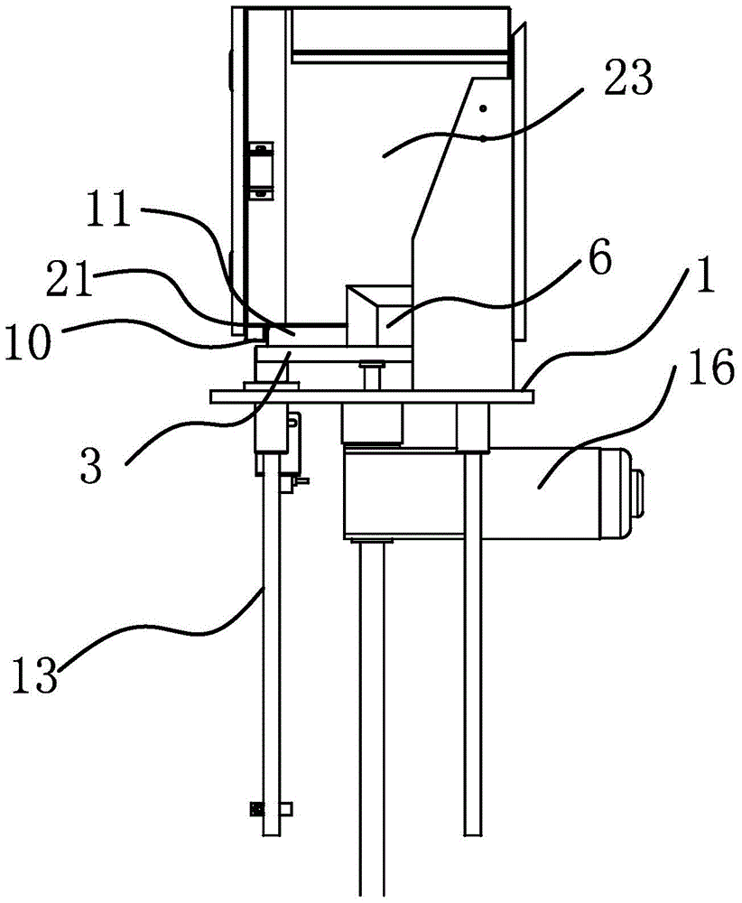
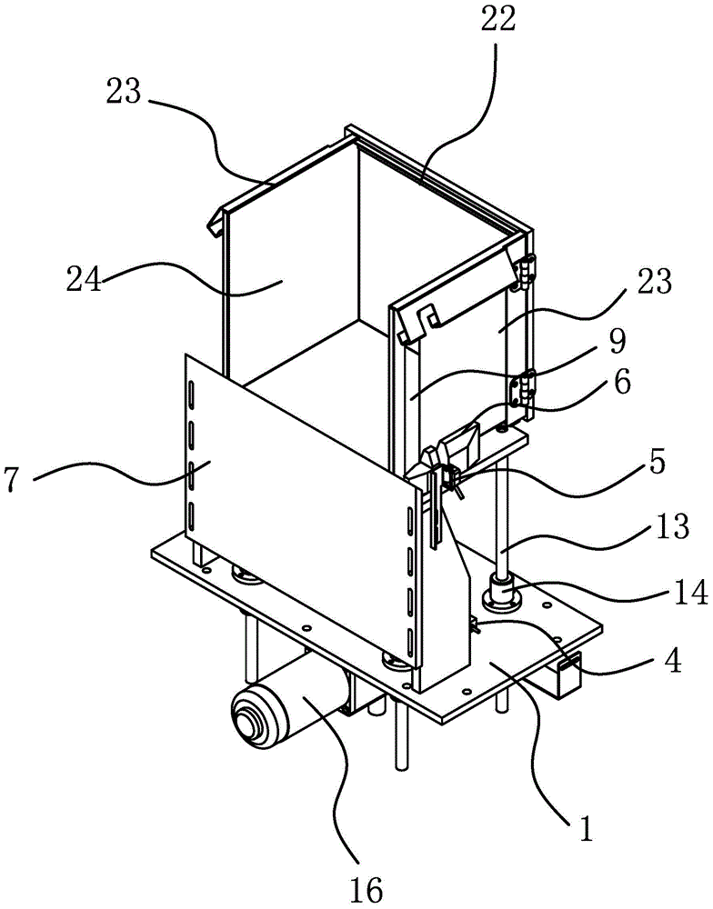
[0024] Such as figure 1 , figure 2 , image 3As shown, the conduit feeding device includes a frame 1 and a silo 2 for placing the conduits. The frame 1 is provided with a support plate 3, and between the frame 1 and the support plate 3 is provided a Drive mechanism for vertical lifting. In this embodiment, the driving mechanism includes a motor 16, a screw and a nut, the motor 16 is fixed on the frame 1, the output end of the motor 16 is connected with the screw, the screw is arranged vertically, and the nut is fixed on the support plate 3 and threaded with the lead screw. The conduit feeding device also includes several guide posts 13 arranged vertically, the frame 1 is provided with a guide sleeve 14 corresponding t...


PUM


Abstract

The invention provides a catheter feeding device, and belongs to the technical field of production equipment for medical instruments. The technical problem that an existing catheter feeding device is low in feeding efficiency is solved. The catheter feeding device comprises a rack and a stock bin used for placing catheters, a supporting plate is arranged on the rack, and a driving mechanism is arranged between the rack and the supporting plate and can drive the supporting plate to ascend or descend in the vertical direction; the stock bin is placed on the supporting plate, a first sensor used for detecting whether the stocking bin is located at the lowest position or not is arranged on the rack, a through groove is formed in the side wall of the stock bin in the vertical direction, a second sensor is arranged on the rack, detection signals transmitted by the second sensor can be transmitted through the through groove to be irradiated to the catheters in the stock bin, and a positioning block is arranged on the supporting plate and capable of positioning the stock bin so that the signal transmitting end of the second sensor can be aligned to the through groove. The stock bin can be replaced fast, and then the feeding efficiency of the catheter feeding device can be improved.

Description

technical field [0001] The invention belongs to the technical field of medical device production equipment, and relates to a catheter feeding device. Background technique [0002] An infusion set is a commonly used medical device, which generally includes a medical catheter, a puncture device, a drip funnel, a flow regulator and a liquid medicine filter. Infusion sets are usually for one-time use. As the demand for infusion sets in hospitals at all levels continues to increase, traditional manual assembly can no longer meet production needs and is gradually replaced by automated assembly equipment and production processes. The assembly speed of automated assembly equipment is relatively fast, and the corresponding requirements for the supply speed of catheters are also relatively high. [0003] Chinese patent CN 203006470U discloses a feeding mechanism for medical vial insertion needle catheters. When in use, the catheters are first loaded into the silo, and then the hopper...

Claims


Application Information

Patent Timeline
Patent Type & Authority Patents(China)
IPC IPC(8): B65G47/74
Inventor 林军华
Owner MAIDER MEDICAL IND EQUIP
Learn More