
Rotary wing blade type flapping wing air vehicle

A flapping wing aircraft and rotary wing technology, applied in the aviation field, can solve problems such as limited lift efficiency and poor movement continuity, and achieve the effect of strong maneuverability and high efficiency

Inactive Publication Date: 2015-03-25
高淑欣
View PDF9 Cites 8 Cited by
  • Summary
  • Abstract
  • Description
  • Claims
  • Application Information

AI Technical Summary

Problems solved by technology

Wings flutter up and down, there is a turning process, and the movement continuity is poor; the Chinese patent No. ZL200910073435.8 discloses a flapping wing lift generating device with a relatively complicated structure that relies on the flapping wing lifting mechanism to reset the flapping wing sheet, although the efficiency is relatively high. The traditional flapping wing is higher, but during the flapping process, only the middle position of the fin is in the horizontal position. At other times, there is an angle between the fin and the horizontal plane. The further away from the middle position, the larger the angle is, and the lift generated is the fin The vertical component of the force, the horizontal component becomes a loss, and the efficiency of generating lift is also limited

Method used


Image

  • Rotary wing blade type flapping wing air vehicle
  • Rotary wing blade type flapping wing air vehicle
  • Rotary wing blade type flapping wing air vehicle

Examples


Embodiment Construction

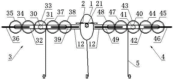
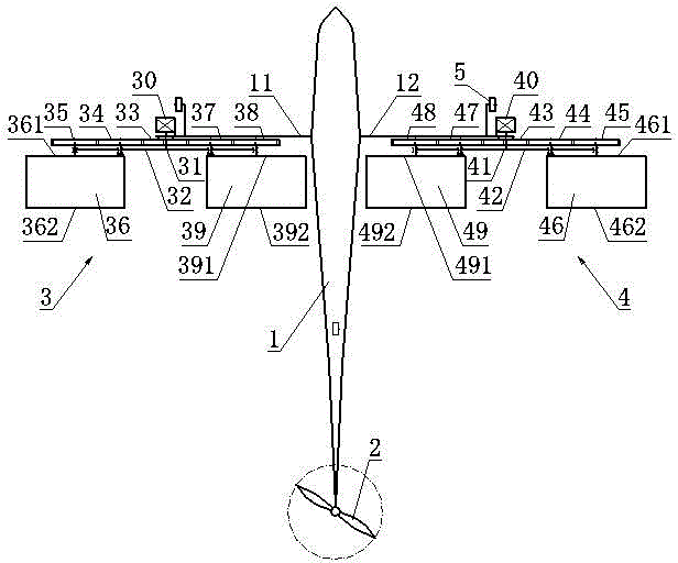
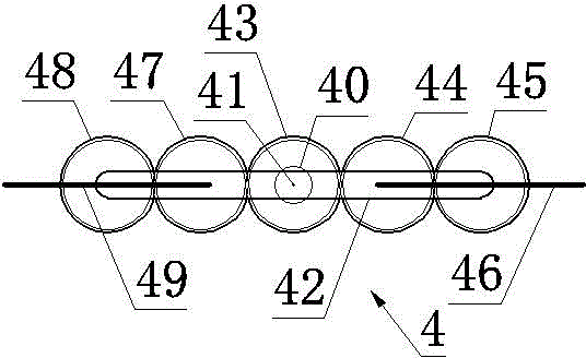
[0013] now attached Figure 1~5 The present invention is specifically described as follows: a flapping-wing aircraft with rotating blades mainly consists of a fuselage 1, a tail propeller 2, a left-rotating flapping-wing device 3, a right-rotating flapping-wing device 4, and an undercarriage 5. The fuselage 1 is equipped with a control system, an automatic navigation autonomous flight instrument and a remote control system. The aircraft adopts a combination of an automatic navigation autonomous flight mode and a remote control flight mode. Fly in autonomous flight mode. The left-rotating flapping-wing device 3 and the right-rotating flapping-wing device 4 have the same structure, parameters and working principle and are symmetrically arranged on the left and right brackets 11 and 12 protruding from the left and right sides of the fuselage 1 to generate lift. and thrust. The tail propeller 2 is driven by a small motor 21, and the rotation plane of the tail propeller 2 can be ...


PUM


Abstract

The invention discloses a rotary wing blade type flapping wing air vehicle belonging to the technical field of aviation. The rotary wing blade type flapping wing air vehicle mainly comprises an air vehicle body, a tail rotor, a left rotary flapping wing device, a right rotary flapping wing device and an undercarriage, wherein the air vehicle body is internally matched with an operation control system, a self-navigated autonomous flight instrument and a remote control system; the left rotary flapping wing device and the right rotary flapping wing device are same in structure, parameter and working principle and are symmetrically arranged at a left support and a right support extending at the left and right sides of the air vehicle body; the tail rotor is driven by a small motor; the right rotary flapping wing device comprises an engine, a main shaft, a rotary arm, a central fixed gear, a first near-center gear, a first remote-center gear, a first wing blade, a second near-center gear, a second remote-center gear and a second wing blade; the meshing transmission ratio of all gears is 1:1; and the first wing blade and the second wing blade alternately upwards and upwards rush to generate a forward thrust force and an upward thrust force. The rotary wing blade type flapping wing air vehicle is used for meeting the requirements of aerial photography, agriculture, forestry and animal husbandry works and military affairs.

Description

technical field [0001] A flapping-wing aircraft with rotating blades belongs to the technical field of aviation, and in particular relates to a flapping-wing aircraft. Background technique [0002] The wings of a traditional flapping-wing aircraft flutter according to a circular arc trajectory. When the wings flap up and down, a part of the aerodynamic component is generated in the horizontal horizontal direction. This horizontal component has no positive effect on the forward movement and lift-off of the flapping-wing aircraft. The effect is a loss of power. Wings flutter up and down, there is a turning process, and the movement continuity is poor; the Chinese patent No. ZL200910073435.8 discloses a flapping wing lift generating device with a relatively complicated structure that relies on the flapping wing lifting mechanism to reset the flapping wing sheet, although the efficiency is relatively high. The traditional flapping wing is higher, but during the flapping process...

Claims


Application Information

Patent Timeline
IPC IPC(8): B64C33/02
Inventor 王志成
Owner 高淑欣
Learn More