
Calibration method and device used for laser processing system

A technology of laser processing and calibration method, applied in laser welding equipment, metal processing equipment, manufacturing tools and other directions, can solve the problems of large calibration error, affect processing effect, and large calibration cost, and achieve simple production method, cost saving and price. low cost effect

Active Publication Date: 2015-03-25
BEIJING LUSTER LIGHTTECH
View PDF8 Cites 48 Cited by
  • Summary
  • Abstract
  • Description
  • Claims
  • Application Information

AI Technical Summary

Problems solved by technology

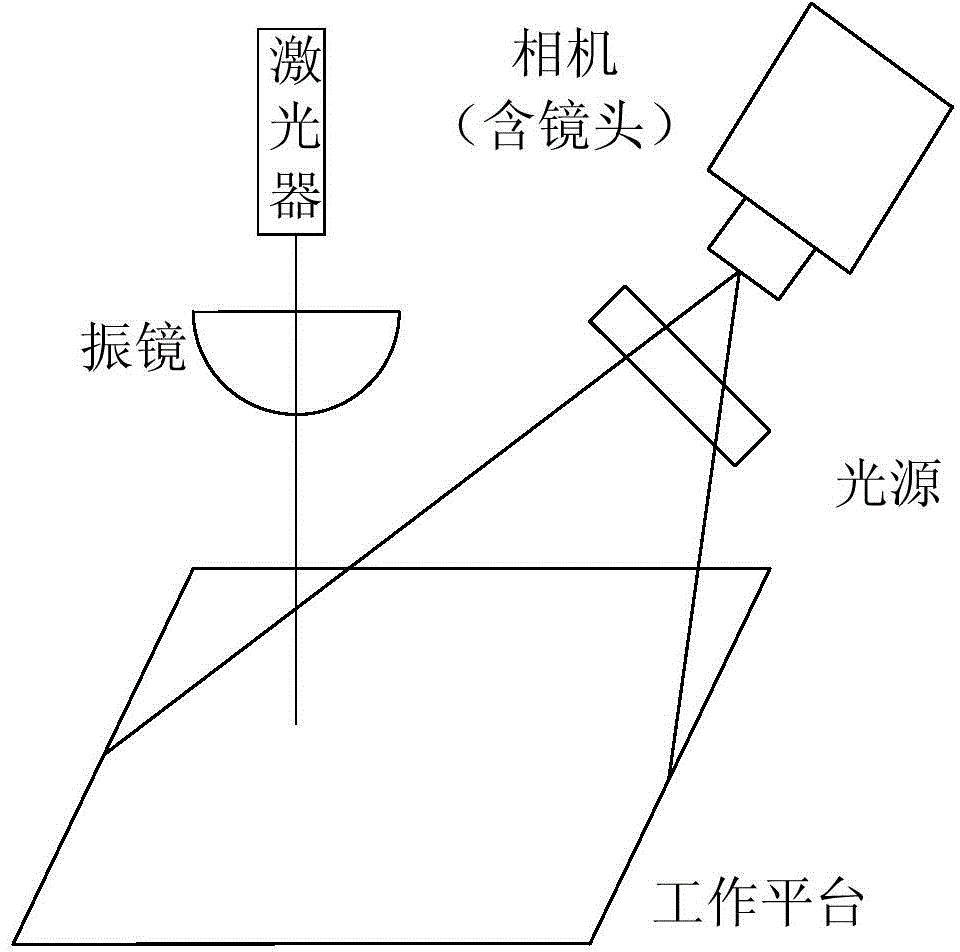
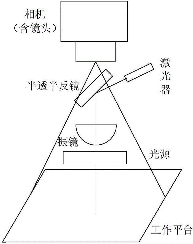
[0004] but, figure 1 During the calibration process of the laser processing system, the target needs to be used for distortion correction, and the price of the target is relatively expensive, resulting in a large calibration cost; and figure 2 When the laser processing system is calibrated, distortion correction is no longer performed. In this case, due to the influence of lens distortion and projection distortion of the camera itself, the calibration error is large, which affects the processing effect.

Method used


Image

  • Calibration method and device used for laser processing system
  • Calibration method and device used for laser processing system
  • Calibration method and device used for laser processing system

Examples


Embodiment Construction

[0076] Reference will now be made in detail to the exemplary embodiments, examples of which are illustrated in the accompanying drawings. When the following description refers to the accompanying drawings, the same numerals in different drawings refer to the same or similar elements unless otherwise indicated. The implementations described in the following exemplary examples do not represent all implementations consistent with the present invention. Rather, they are merely examples of apparatuses and methods consistent with aspects of the invention as recited in the appended claims.

[0077] In order to solve the existing technology, figure 1 When the laser processing system is calibrated, due to the need to use the target, it leads to the problem of high calibration cost, and figure 2 When the laser processing system is calibrated, the calibration error is large, which affects the processing effect. The application discloses a calibration method for the laser processing sy...


PUM


Abstract

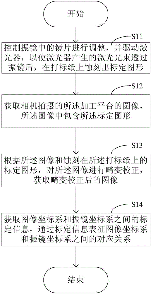
The invention discloses a calibration method and device used for a laser processing system. The calibration method includes the steps that firstly, a lens in a galvanometer is controlled to be adjusted according to a calibration picture which is edited in advance, a laser device is driven, a laser beam generated by the laser device is made to penetrate through the galvanometer, and the calibration picture is etched on marking paper which is placed on a processing platform in advance; secondly, an image, photographed by a camera, of the processing platform is obtained, and the image includes the calibration picture; thirdly, distortion correction is conducted according to the image and the calibration picture etched on the marking paper, and the corresponding relation between an image coordinate system and a galvanometer coordinate system is obtained. According to the calibration method and device used for the laser processing system, distortion correction is achieved through the calibration picture on the marking paper, a target does not need to be used, cost is saved under the premise that precision is ensured, and the calibration operation is simplified.

Description

technical field [0001] The present disclosure relates to the technical field of laser processing, in particular to a calibration method and device for a laser processing system. Background technique [0002] Laser processing refers to focusing the energy of the laser on a specific focus to achieve a high energy density, and to realize material processing by photothermal effect, such as laser marking, laser welding, laser cutting and laser drilling. Laser processing has the advantages of fast processing speed, small surface deformation and application to a variety of materials, and is used in many industrial fields. In recent years, in order to improve the processing accuracy, efficiency and stability of the equipment, it has become an inevitable trend to introduce machine vision into the laser processing system. At present, the structure schematic diagram of the more common laser processing system with machine vision is as follows: figure 1 and figure 2 As shown, wherein...

Claims


Application Information

Patent Timeline
IPC IPC(8): B23K26/035
CPCB23K26/046
Inventor 戴志强杨艺马丽胡坤钟克洪
Owner BEIJING LUSTER LIGHTTECH
Learn More